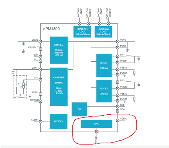
I am working on a project where I am using the npm1300 with host nrf5340. The BUCK1 powers a sensor and BUCK2 powers the nrf5340. I have a SPDT switch connected to GPIO0 and GND and the third pin is floating. I don't have a pull up or pull down on the GPIO0 line. I want to use the switch as the On/Off control for both BUCK1 and BUCK2. I used the zephyr device tree overlay file to do this configuration for me but I can't find any documentation to configure it as input with pull up (optionally also enable the debounce) and then enable the BUCKENCTRL as mentioned in the npm1300 datasheet to use the GPIO0 as on off control.
This is the overlay file that I managed to generate with the nrf PowerUp application but I don't know which flags go into the gpio to configure as above.
/*
 * Copyright (C) 2023 Nordic Semiconductor ASA
 * SPDX-License-Identifier: Apache-2.0
 */

#include <dt-bindings/regulator/npm1300.h>
#include <zephyr/dt-bindings/input/input-event-codes.h>

&arduino_i2c {
    npm1300_ek_pmic: pmic@6b {
        compatible = "nordic,npm1300";
        reg = <0x6b>;


        // ship-to-active-time = <96>;


        // long-press-reset = "one_button";


        npm1300_ek_gpio: gpio-controller {
            compatible = "nordic,npm1300-gpio";
            gpio-controller;
            #gpio-cells = <2>;
            ngpios = <5>;
        };

        npm1300_ek_regulators: regulators {
            compatible = "nordic,npm1300-regulator";


            npm1300_ek_buck1: BUCK1 {
                regulator-min-microvolt = <1000000>;
                regulator-max-microvolt = <3300000>;

                retention-microvolt = <1000000>;
                enable-gpios = <&npm1300_ek_gpio 0 GPIO_ACTIVE_HIGH>;


            };


            npm1300_ek_buck2: BUCK2 {
                regulator-min-microvolt = <1000000>;
                regulator-max-microvolt = <3300000>;

                retention-microvolt = <1000000>;
                enable-gpios = <&npm1300_ek_gpio 0 GPIO_ACTIVE_HIGH>;


            };


            npm1300_ek_ldo1: LDO1 {
                regulator-min-microvolt = <1000000>;
                regulator-max-microvolt = <3300000>;

                regulator-initial-mode = <NPM1300_LDSW_MODE_LDSW>;


            };


            npm1300_ek_ldo2: LDO2 {
                regulator-min-microvolt = <1000000>;
                regulator-max-microvolt = <3300000>;

                regulator-initial-mode = <NPM1300_LDSW_MODE_LDSW>;


            };

        };


        npm1300_ek_charger: charger {
            compatible = "nordic,npm1300-charger";
            term-microvolt = <4200000>;
            term-warm-microvolt = <4000000>;
            // term-current-percent = <10>;
            current-microamp = <500000>;
            // trickle-microvolt = <2900000>;
            dischg-limit-microamp = <270000>;
            vbus-limit-microamp = <500000>;
            thermistor-ohms = <10000>;
            thermistor-beta = <3380>;

            charging-enable;
            vbatlow-charge-enable;
        };


        npm1300_ek_leds: leds {
            compatible = "nordic,npm1300-led";
            nordic,led0-mode = "error";
            nordic,led1-mode = "charging";
            nordic,led2-mode = "host";
        };

        npm1300_ek_buttons: buttons {
            compatible = "gpio-keys";
            pmic_button0: pmic_button_0 {
                gpios = <&npm1300_ek_gpio 0 GPIO_ACTIVE_LOW>;
                label = "Pmic button switch 0";
                zephyr,code = <INPUT_KEY_0>;
            };
        };
    };
};
I have managed to configure the gpio manually by using the mfd driver file (mfd_npm1300.c) from zephyr as follows, this works well but is there a better way through zephyr overlay?
uint8_t reg_val = 0;
err = mfd_npm1300_reg_read(pmic, 0x06U, 0x00U, ®_val);
if (err < 0) {
LOG_ERR("Failed to read PMIC register: %d", err);
return 0;
}
LOG_INF("PMIC GPIO0 mode: 0x%02X", reg_val);
err = mfd_npm1300_reg_write(pmic, 0x06U, 0x19U, 1); // enable debounce for gpio0
if (err < 0) {
LOG_ERR("Failed to write PMIC register: %d", err);
return 0;
}
reg_val = 0;
err = mfd_npm1300_reg_read(pmic, 0x06U, 0x19U, ®_val);
LOG_INF("PMIC GPIO0 debounce: 0x%02X", reg_val);
err = mfd_npm1300_reg_write(pmic, 0x06U, 0x0FU, 0); // disable PD for gpio0
if (err < 0) {
LOG_ERR("Failed to write PMIC register: %d", err);
return 0;
}
reg_val = 0;
err = mfd_npm1300_reg_read(pmic, 0x06U, 0x0FU, ®_val);
LOG_INF("PMIC GPIO0 PD: 0x%02X", reg_val);
err = mfd_npm1300_reg_write(pmic, 0x06U, 0x0AU, 1); // enable PU for gpio0
if (err < 0) {
LOG_ERR("Failed to write PMIC register: %d", err);
return 0;
}
reg_val = 0;
err = mfd_npm1300_reg_read(pmic, 0x06U, 0x19U, ®_val);
LOG_INF("PMIC GPIO0 PU: 0x%02X", reg_val);
err = mfd_npm1300_reg_write(pmic, 0x04U, 0x0CU, 0b00001001); // set gpio0 for on/off control buck1/2
if (err < 0) {
	LOG_ERR("Failed to write PMIC register: %d", err);
	return 0;
}
reg_val = 0;
err = mfd_npm1300_reg_read(pmic, 0x04U, 0x0CU, ®_val);
LOG_INF("PMIC BUCKENCTRL: 0x%02X", reg_val);I have tried everything with the overlay file but I always get the GPIO0 mode as 0x03 which corresponds to GPI Rising Edge Event. Can someone explain what is going wrong here?