Hello!
I'm currently working with the nRF7002 Wi-Fi chip on a custom board. The MCU used is STM32H573ZIT6, and the software is Zephyr 4.0, specifically using the Wi-Fi shell for initial testing.
Previously, I successfully used STM32H573I-DK + nRF7002-EK, and everything worked flawlessly. However, after migrating to our custom board, I encountered some serious stability issues.
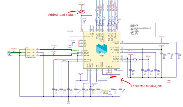
Initially, there were a few mistakes in the schematic, which I’ve since fixed (I also replaced the nRF7002 IC to eliminate any potential hardware damage from earlier mistakes). Now the Wi-Fi chip boots without errors, but the functionality is unstable:
- It can scan for Wi-Fi networks once (successfully).
- After the first scan, the interface stops responding completely.
- It is unable to connect to any access point.
To eliminate possible issues with power or software, I wired an nRF7002-EK directly to our custom board (connecting GPIO, SPI, and power), bypassing the onboard nRF7002 chip. In this configuration, everything works perfectly, confirming that the issue is likely with our custom implementation of the nRF7002.
I also tried swapping antennas and made our design as close as possible to the nRF7002-EK. Unfortunately, the result is the same - the custom board fails, while the evaluation kit works.
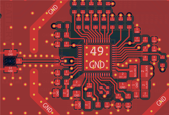
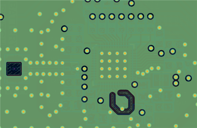
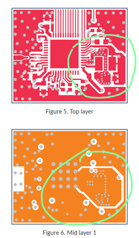
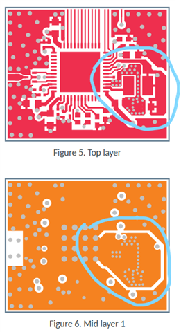
We are aware that there are some layout issues on our board, and while I tried adding additional capacitors to the internal DC/DC, it had no effect. I'm not sure how much the layout may impact this kind of instability.
Attaching logs, schematic, and layout files (with fixes marked).
Any advice or ideas on what else to check would be really appreciated!
Thanks!
Failed scan:
uart:~$ wifi scan
Scan requested
[00:00:37.425,000] <dbg> wifi_nrf: zep_shim_pr_dbg: nrf_wifi_hal_ctrl_cmd_send: caller 0x8065a0d
[00:00:37.425,000] <dbg> wifi_nrf_bus: rpu_wrsr2: Written 0x1 to WRSR2
[00:00:37.426,000] <dbg> wifi_nrf_bus: spim_read_reg: err: 0 -> 0 1 1 1 1 1
[00:00:37.426,000] <dbg> wifi_nrf_bus: spim_wait_while_rpu_wake_write: RDSR2 = 0x1
[00:00:37.426,000] <dbg> wifi_nrf_bus: spim_read_reg: err: 0 -> 0 0 0 0 0 0
[00:00:37.426,000] <dbg> wifi_nrf_bus: _spim_wait_while_rpu_awake: RDSR1 = 0x0
[00:00:37.427,000] <dbg> wifi_nrf_bus: spim_read_reg: err: 0 -> 0 0 0 0 0 0
[00:00:37.427,000] <dbg> wifi_nrf_bus: _spim_wait_while_rpu_awake: RDSR1 = 0x0
[00:00:37.428,000] <dbg> wifi_nrf_bus: spim_read_reg: err: 0 -> 0 0 0 0 0 0
[00:00:37.428,000] <dbg> wifi_nrf_bus: _spim_wait_while_rpu_awake: RDSR1 = 0x0
[00:00:37.429,000] <dbg> wifi_nrf_bus: spim_read_reg: err: 0 -> 0 0 0 0 0 0
[00:00:37.429,000] <dbg> wifi_nrf_bus: _spim_wait_while_rpu_awake: RDSR1 = 0x0
[00:00:37.430,000] <dbg> wifi_nrf_bus: spim_read_reg: err: 0 -> 0 2 2 2 2 2
[00:00:37.430,000] <dbg> wifi_nrf_bus: _spim_wait_while_rpu_awake: RDSR1 = 0x2
[00:00:37.431,000] <dbg> wifi_nrf_bus: spim_read_reg: err: 0 -> 0 2 2 2 2 2
[00:00:37.431,000] <dbg> wifi_nrf_bus: _spim_wait_while_rpu_awake: RDSR1 = 0x2
[00:00:37.432,000] <dbg> wifi_nrf_bus: spim_read_reg: err: 0 -> 0 2 2 2 2 2
[00:00:37.432,000] <dbg> wifi_nrf_bus: _spim_wait_while_rpu_awake: RDSR1 = 0x2
[00:00:37.433,000] <dbg> wifi_nrf_bus: spim_read_reg: err: 0 -> 0 2 2 2 2 2
[00:00:37.433,000] <dbg> wifi_nrf_bus: _spim_wait_while_rpu_awake: RDSR1 = 0x2
[00:00:37.434,000] <dbg> wifi_nrf_bus: spim_read_reg: err: 0 -> 0 6 6 6 6 6
[00:00:37.434,000] <dbg> wifi_nrf_bus: _spim_wait_while_rpu_awake: RDSR1 = 0x6
[00:00:37.435,000] <dbg> wifi_nrf: zep_shim_pr_dbg: umac_cmd_cfg: Command 0 sent to RPU
[00:00:37.437,000] <dbg> wifi_nrf: zep_shim_pr_dbg: nrf_wifi_fmac_event_callback: Event type 3 recd
[00:00:37.438,000] <dbg> wifi_nrf: zep_shim_pr_dbg: umac_event_ctrl_process: Event 257 received from UMAC
[00:00:37.438,000] <dbg> wifi_nrf: zep_shim_pr_dbg: umac_event_ctrl_process: Event 257 processed
[00:00:37.438,000] <dbg> wifi_nrf: zep_shim_pr_dbg: nrf_wifi_fmac_event_callback: Event type 3 recd
[00:00:37.438,000] <dbg> wifi_nrf: zep_shim_pr_dbg: umac_event_ctrl_process: Event 292 received from UMAC
[00:00:37.438,000] <dbg> wifi_nrf: zep_shim_pr_dbg: umac_event_ctrl_process: Command 0 -> status 0
[00:00:37.438,000] <dbg> wifi_nrf: zep_shim_pr_dbg: umac_event_ctrl_process: Event 292 processed
Scan request failed (-116)
uart:~$
Failed connection:
Starting connect...
Wi-Fi connect request successfully sent.
[00:00:02.576,000] <dbg> wifi_module: wifi_request_connect: Connection requested
[00:00:15.382,000] <err> wifi_nrf: nrf_wifi_fmac_chg_vif_state: RPU is unresponsive for 10 sec
[00:00:15.382,000] <err> wifi_nrf: nrf_wifi_if_stop_zep: nrf_wifi_fmac_chg_vif_state failed
[00:00:15.383,000] <inf> wifi_supplicant: Network interface 2 (0x20001d98) down
[00:00:17.385,000] <inf> wifi_nrf_bus: SPIM spi@44002000: freq = 8 MHz
[00:00:17.385,000] <inf> wifi_nrf_bus: SPIM spi@44002000: latency = 0
[00:00:17.698,000] <inf> wifi_supplicant: Network interface 2 (0x20001d98) up