Dear all,
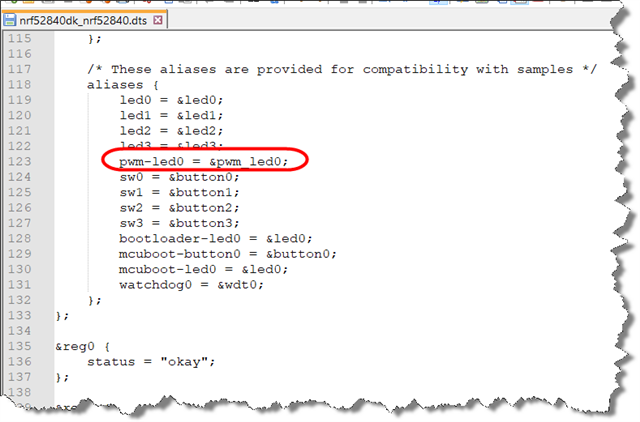
after cutting the SB bridge to the QSPI chip and close the ones to get the pin free and disabled also qspi inside the nRF52840dk_nrf52840.overlay file I'm unable to get the PWM output on P0.22, this seems locked to pin P0.13 related LED1 on the DK board.
Here below my relevant part of the overaly file:
&pwm0 {
    status = "okay";
	pinctrl-0 = <&pwm0_buzzer_default>;
	pinctrl-1 = <&pwm0_buzzer_sleep>;
	pinctrl-names = "default", "sleep";
};

&qspi {
    status = "disabled";
};

&pinctrl{
    pwm0_buzzer_default: pwm0_buzzer_default {
        group1 {
            psels = <NRF_PSEL(PWM_OUT0, 0, 22)>;
        };
	};

	pwm0_buzzer_sleep: pwm0_buzzer_sleep {
		group1 {
			psels = <NRF_PSEL(PWM_OUT0, 0, 22)>;
			low-power-enable;
		};
	};
};
in my C code I'm using this to retrieve the handle and manage the signal:
#define PWM_LED0        DT_ALIAS(pwm_led0)
static const struct pwm_dt_spec buzzer_pwm = PWM_DT_SPEC_GET(PWM_LED0);
kindly someone could let me know what is wrong?
Thanks!!
F.


