nRF52840 DK unable to route the PWM0 default line P0.13 on P0.22

Dear all,

after cutting the SB bridge to the QSPI chip and close the ones to get the pin free and disabled also qspi inside the nRF52840dk_nrf52840.overlay file I'm unable to get the PWM output on P0.22, this seems locked to pin P0.13 related LED1 on the DK board.

Here below my relevant part of the overaly file:

&pwm0 {
    status = "okay";
	pinctrl-0 = <&pwm0_buzzer_default>;
	pinctrl-1 = <&pwm0_buzzer_sleep>;
	pinctrl-names = "default", "sleep";
};

&qspi {
    status = "disabled";
};

&pinctrl{
    pwm0_buzzer_default: pwm0_buzzer_default {
        group1 {
            psels = <NRF_PSEL(PWM_OUT0, 0, 22)>;
        };
	};

	pwm0_buzzer_sleep: pwm0_buzzer_sleep {
		group1 {
			psels = <NRF_PSEL(PWM_OUT0, 0, 22)>;
			low-power-enable;
		};
	};
};

in my C code I'm using this to retrieve the handle and manage the signal:

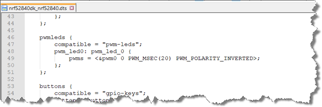
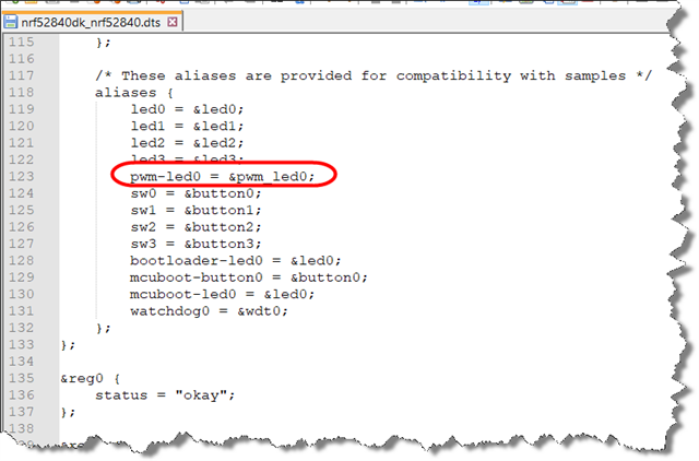
#define PWM_LED0        DT_ALIAS(pwm_led0)
static const struct pwm_dt_spec buzzer_pwm = PWM_DT_SPEC_GET(PWM_LED0);

kindly someone could let me know what is wrong?

Thanks!!

F.

Parents
  • Hi Fabio,

    I think what is missing is that you have not set the aliases in the overlay file. You need to define a pwmleds node and the pwm_led0 label, and add the alias for pwm-led0

    The samples in nRF Connect SDK and Zephyr OS uses fixed aliases for devicetree nodes. Therefore, to ensure that samples find these aliases, it’s crucial to add aliases in the board devicetree file and ensure that DT_ALIAS(pwm_led0) in your code points to the correct node. This is explained here: https://academy.nordicsemi.com/courses/nrf-connect-sdk-intermediate/lessons/lesson-3-adding-custom-board-support/topic/exercise-1/#Exercise-steps:~:text=%7D%3B-,8.4.3%20Adding%20PWM.,-Let%E2%80%99s%20enable%20a 

    Here is also an old thread that you could refer: (+) Using PWM with nrf52840DK on pin 0.20 - Nordic Q&A - Nordic DevZone - Nordic DevZone 

    You might need to add the following in your overlay:


    {
        aliases {
            pwm-led0 = &pwm_led0;
        };
    
        pwmleds {
            compatible = "pwm-leds";
            pwm_led0: pwm_led_0 {
                pwms = <&pwm0 0 PWM_MSEC(20) PWM_POLARITY_NORMAL>;
            };
        };
    };
    Regards,
    Swathy
  • Dear SwRa,

    thanks for your reply!!

    About the overlay file I've not added again the definition for the pwmleds because (in my thinking, correct me if this is not right) was already set inside the nRF52840dk_nrf52840.dts file and I've no change to do inside this part...

    also aliases is already set:

    could you please let me know why I've also to specify this part again inside the overlay file even it is equal to the ones into the nRF52840 eval board dts file? What I'm missing?

    I'm not using a custom board, I would simply rerouted the previous signal to new one on a nRF52840 DK v3.0.0 evaluation board, so I updated the pinctrl definitions and linked them to the overlay for pwm0. I also physically disconnected the onboard QSPI memory by cutting the relevant traces and bridging the necessary lines, so that P0.17, P0.21, P0.22, P0.23, P0.19, and P0.20 are now available as GPIOs.

    Could you please let me know more on this?

    I'm also working in a real custom board (different PCB based on nRF52840 SoC) and I was able to route the pwm signal on the nRF52840 P0.22 pin of course in my dts board file I've included also the pwmleds and aliases definition.

    Thanks for you help!!

    Best regards.

    Fabio

Reply
  • Dear SwRa,

    thanks for your reply!!

    About the overlay file I've not added again the definition for the pwmleds because (in my thinking, correct me if this is not right) was already set inside the nRF52840dk_nrf52840.dts file and I've no change to do inside this part...

    also aliases is already set:

    could you please let me know why I've also to specify this part again inside the overlay file even it is equal to the ones into the nRF52840 eval board dts file? What I'm missing?

    I'm not using a custom board, I would simply rerouted the previous signal to new one on a nRF52840 DK v3.0.0 evaluation board, so I updated the pinctrl definitions and linked them to the overlay for pwm0. I also physically disconnected the onboard QSPI memory by cutting the relevant traces and bridging the necessary lines, so that P0.17, P0.21, P0.22, P0.23, P0.19, and P0.20 are now available as GPIOs.

    Could you please let me know more on this?

    I'm also working in a real custom board (different PCB based on nRF52840 SoC) and I was able to route the pwm signal on the nRF52840 P0.22 pin of course in my dts board file I've included also the pwmleds and aliases definition.

    Thanks for you help!!

    Best regards.

    Fabio

Children
No Data
Related