Unintended pulse at start up of a PWM output

Hello,

On nRF52832, I implemented a code with PWM output at P0.07.

Here is the section at my overlay:

pwmleds {
        compatible = "pwm-leds";
        pwm_led0: pwm_led_0 {
            pwms = <&pwm0 0 PWM_MSEC(0) PWM_POLARITY_NORMAL >;
        };
    };
&pwm0 {
    status = "okay";
    pinctrl-0 = <&pwm0_custom>;
    pinctrl-1 = <&pwm0_csleep>;
    pinctrl-names = "default", "sleep";
};
&pinctrl {
    pwm0_custom: pwm0_custom {
        group1 {
            psels = <NRF_PSEL(PWM_OUT0, 0, 7)>;
            nordic,invert;
        };
    };  
   
    pwm0_csleep: pwm0_csleep {
        group1 {
            psels = <NRF_PSEL(PWM_OUT0, 0, 7)>;
            low-power-enable;
        };
    };

    uart0_default: uart0_default {
        group1 {
            psels = <NRF_PSEL(UART_TX, 0, 6)>,
                <NRF_PSEL(UART_RX, 0, 8)>;
        };
    };

    uart0_sleep: uart0_sleep {
        group1 {
            psels = <NRF_PSEL(UART_TX, 0, 6)>,
                <NRF_PSEL(UART_RX, 0, 8)>;
            low-power-enable;
        };
    };
};
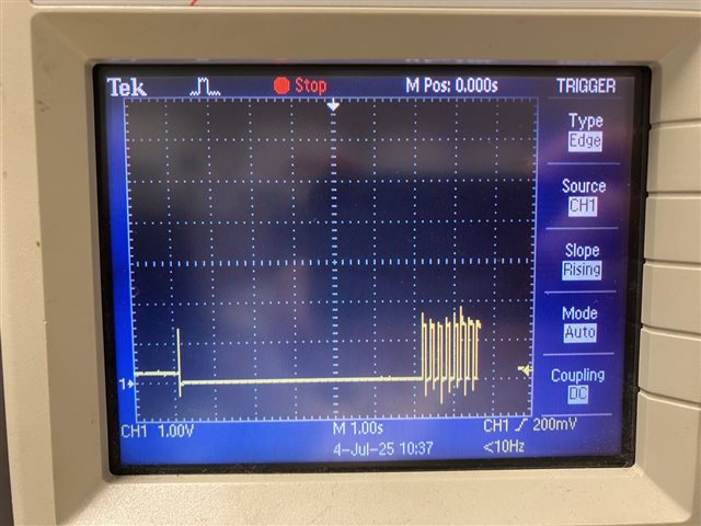
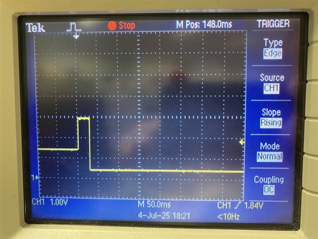
I can observe a 25-40ms pulse at the pin during startup. I tried to add this pin as "gpio-leds" also but still seeing the pulse.
As shown in the above overlay configuration, I disabled UART_CTS function also as it is configured as as P0.07 pin as default.

Do you have any suggestion? Thanks!
Parents Reply
  • Hello,

    Attached please find the capture of the waveform. A pulse is observed at ~1s.
    The waveform was measured at nRF52dk PCA10040, P0.17, i.e. control of LED1. This confirms the issue is not related to P0.07.

    The waveform is captured by running the pwm example code, with the following added in DT overlay. No modification was done in the example code.

    / {
    	zephyr,user {
    		io-channels = <&adc 0>;
    	};
        pwmleds {
    		compatible = "pwm-leds";
    		pwm_led0: pwm_led_0 {
    			pwms = <&pwm0 0 PWM_MSEC(0) PWM_POLARITY_NORMAL >;
    		};
    	};
    };

Children
  • Thank you! Just to confirm, is this the code sample that you are using? zephyr/samples/drivers/led/pwm/

  • Hello Benjamin,

    Yes, this is the sample code that I tested.

  • Alright, I have tested with the setup you described and I cannot immediately reproduce the issue.

    1. What are you trying to achieve when setting PWM period to 0 in the overlay file?

    2. Could you zoom in on the pulse on the capture?

  • Hello Benjamin,

    1. I thought this is the a way that I can get the PWM output pin as low level after power on. I am fine with any settings in the overlay as I can just change the output frequency by using pwm_set_dt() in my codes.

    BTW, I just changed this period value as PWM_MSEC(20) in the overlay file. In this case I find a much longer pulse high level pulse after power on while running the pwm example. I tried to comment the do while loop in the example code, so it becomes:

    int main(void)
    {
    	const struct device *led_pwm;
    	uint8_t led;
    
    	led_pwm = DEVICE_DT_GET(LED_PWM_NODE_ID);
    	if (!device_is_ready(led_pwm)) {
    		LOG_ERR("Device %s is not ready", led_pwm->name);
    		return 0;
    	}
    
    	if (!num_leds) {
    		LOG_ERR("No LEDs found for %s", led_pwm->name);
    		return 0;
    	}
    
    	// do {
    	// 	for (led = 0; led < num_leds; led++) {
    	// 		run_led_test(led_pwm, led);
    	// 	}
    	// } while (true);
    	return 0;
    }

    In this case, the voltage level appears to be kept as high. Is this an expected behavior even with the setting of PWM_POLARITY_NORMAL?

    2. Please find a capture of the pulse.

Related