Unintended pulse at start up of a PWM output

Hello,

On nRF52832, I implemented a code with PWM output at P0.07.

Here is the section at my overlay:

pwmleds {
        compatible = "pwm-leds";
        pwm_led0: pwm_led_0 {
            pwms = <&pwm0 0 PWM_MSEC(0) PWM_POLARITY_NORMAL >;
        };
    };
&pwm0 {
    status = "okay";
    pinctrl-0 = <&pwm0_custom>;
    pinctrl-1 = <&pwm0_csleep>;
    pinctrl-names = "default", "sleep";
};
&pinctrl {
    pwm0_custom: pwm0_custom {
        group1 {
            psels = <NRF_PSEL(PWM_OUT0, 0, 7)>;
            nordic,invert;
        };
    };  
   
    pwm0_csleep: pwm0_csleep {
        group1 {
            psels = <NRF_PSEL(PWM_OUT0, 0, 7)>;
            low-power-enable;
        };
    };

    uart0_default: uart0_default {
        group1 {
            psels = <NRF_PSEL(UART_TX, 0, 6)>,
                <NRF_PSEL(UART_RX, 0, 8)>;
        };
    };

    uart0_sleep: uart0_sleep {
        group1 {
            psels = <NRF_PSEL(UART_TX, 0, 6)>,
                <NRF_PSEL(UART_RX, 0, 8)>;
            low-power-enable;
        };
    };
};
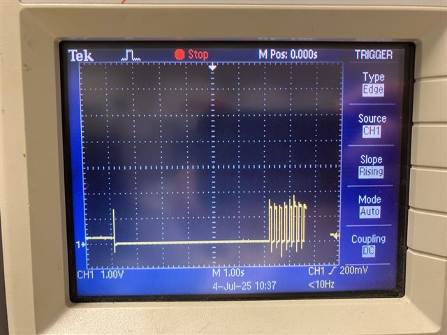
I can observe a 25-40ms pulse at the pin during startup. I tried to add this pin as "gpio-leds" also but still seeing the pulse.
As shown in the above overlay configuration, I disabled UART_CTS function also as it is configured as as P0.07 pin as default.

Do you have any suggestion? Thanks!
Parents Reply Children
  • Hello Benjamin,

    Yes, this is the sample code that I tested.

  • Alright, I have tested with the setup you described and I cannot immediately reproduce the issue.

    1. What are you trying to achieve when setting PWM period to 0 in the overlay file?

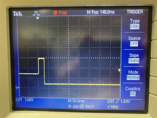
    2. Could you zoom in on the pulse on the capture?

  • Hello Benjamin,

    1. I thought this is the a way that I can get the PWM output pin as low level after power on. I am fine with any settings in the overlay as I can just change the output frequency by using pwm_set_dt() in my codes.

    BTW, I just changed this period value as PWM_MSEC(20) in the overlay file. In this case I find a much longer pulse high level pulse after power on while running the pwm example. I tried to comment the do while loop in the example code, so it becomes:

    int main(void)
    {
    	const struct device *led_pwm;
    	uint8_t led;
    
    	led_pwm = DEVICE_DT_GET(LED_PWM_NODE_ID);
    	if (!device_is_ready(led_pwm)) {
    		LOG_ERR("Device %s is not ready", led_pwm->name);
    		return 0;
    	}
    
    	if (!num_leds) {
    		LOG_ERR("No LEDs found for %s", led_pwm->name);
    		return 0;
    	}
    
    	// do {
    	// 	for (led = 0; led < num_leds; led++) {
    	// 		run_led_test(led_pwm, led);
    	// 	}
    	// } while (true);
    	return 0;
    }

    In this case, the voltage level appears to be kept as high. Is this an expected behavior even with the setting of PWM_POLARITY_NORMAL?

    2. Please find a capture of the pulse.

Related