Incorrect first bit on MOSI during SPI transfer (nRF54L15, Mode 0, prescaler > 2)

Hello,

I'm developing with an nRF54L15 Revision 1 (QFAA-B00). I'm encountering a problem described in the errata:
3.4 [8] SPIM: Wrong data is transmitted on MOSI
(Symptom: When SPIM is used with CPHA=0, prescaler > 2, and the first bit to transmit is '1', the data on MOSI is incorrect).

I am using Zephyr (nRF Connect SDK v3.0.2) and the SPI API (spi_transceive_dt() from <zephyr/drivers/spi.h>).

I have confirmed that the workaround is executed:
USE_WORKAROUND_FOR_ANOMALY_NRF54L_8_NRF54H_212 is defined in the NRFX driver (nrfx_spim.c), and the code performs the actions described in the errata:
- Sets CSNDUR to (prescaler / 2 + 1)
- Writes 0x82 to the SPIM register at offset 0xc84 before starting the transfer
- Resets this register to 0x00 after EVENTS_STARTED

However, even with this workaround active, the first bit problem persists:
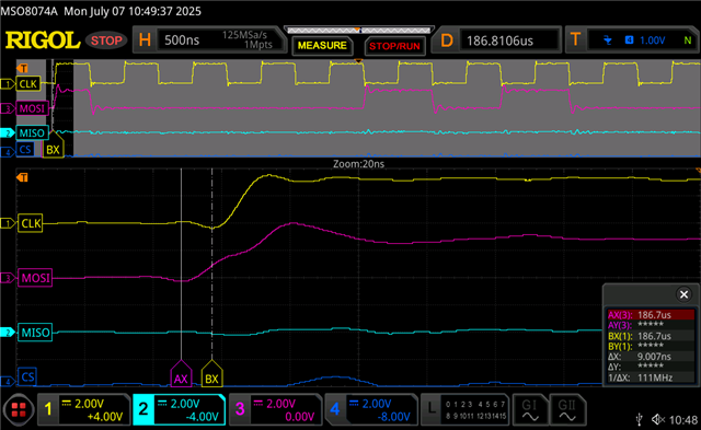
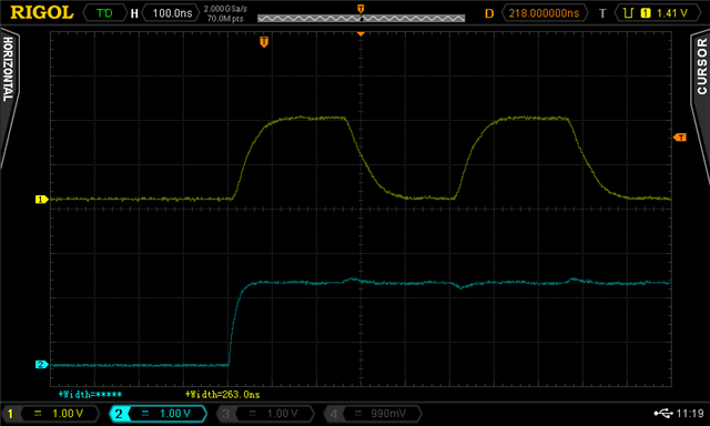
- On the oscilloscope, the MOSI line only transitions to ‘1’ on the rising edge of SCK instead of being centered between clock edges
- As a result, the slave samples the wrong value for the first bit if it is ‘1’.
- This behavior only affects the first 8-bit word after each CSN (SS) activation, and only if the first bit is '1'.
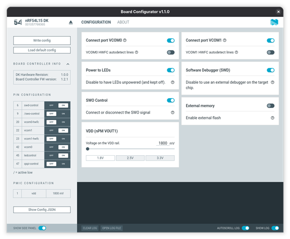
My configuration:
- Custom board, nRF54L15 Revision 1 (QFAA-B00), also tested with Engineering B (QFAA-BB0) – same issue
- SPI frequency: 2 MHz (prescaler = 64)
- SPI mode 0 (CPOL=0, CPHA=0)
- Using instance SPIM00
- Zephyr nRF Connect SDK v3.0.2

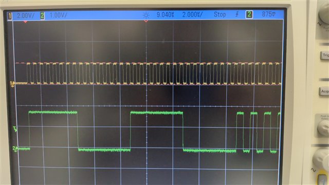
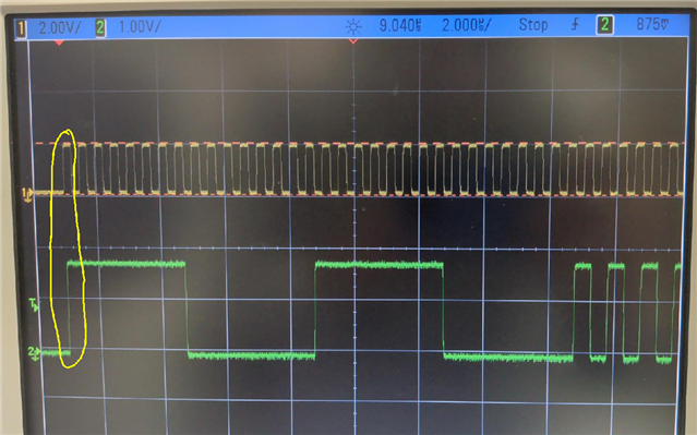
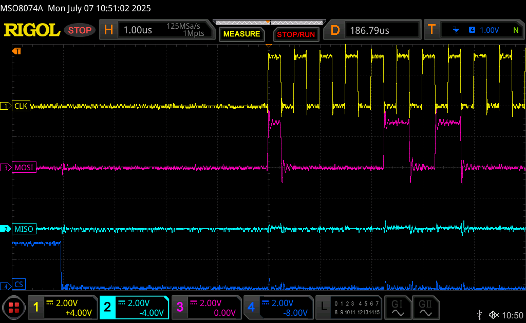
Oscilloscope captures:

The first bit transitions to ‘1’ on the rising edge of SCK instead of being centered between clock edges


Can you confirm if anything else is required on the application (or configuration) side to ensure the workaround is fully effective when using Zephyr’s SPI API? Are there any known limitations or further steps to handle this errata in this context?


Thank you for your support,

Baptiste
  • Hi, have you resolved this issue? I have exactly the same problem with the nRF54L15 DK. MOSI is set about 5 ns before the rising edge of the SCK signal, which is too short for the slave to properly recognize it.

    I’m using nRF SDK 3.0.2 and SPIM00. With SPIM20 the situation is slightly better — MOSI is set 60 ns before the SCK rising edge — but it’s still too little. I need the MOSI line to be set at least half a clock cycle before the SCK edge.

    For now, bit-banged SPI works correctly, but I can only reach about 400 kHz, which is far too low.

  • Hi

    We have not made any progress no. What pins and sample project(s) are you seeing this issue on? I'd like to reproduce it but haven't been able to yet.

    Best regards,

    Simon

  • Hi, to reproduce this issue you need an nRF54L15 DK v1.0.0:
    https://www.nordicsemi.com/Products/Development-hardware/nRF54L15-DK
    https://docs.zephyrproject.org/latest/boards/nordic/nrf54l15dk/doc/index.html

    I see the same problem on different board revisions and on our custom hardware.
    This DK includes an SPI flash module configured in the device tree, so we can use it to reproduce the behavior.

    To get the SPI signal on the header, you must use the board configurator and disable the external memory, as shown here:

    Below is a minimal example that sends data over SPI using the default SPI00 pinout that is:

    SCK P2.1

    MOSI P2.2


    main.cpp

    #include <zephyr/drivers/spi.h>
    
    int main(void)
    {
        const struct device* spi00 = DEVICE_DT_GET(DT_NODELABEL(spi00));
    
        struct spi_config spi_cfg = {
            .frequency = 2000000,
            .operation = SPI_WORD_SET(8) | SPI_TRANSFER_MSB,
            .slave = 0,
            .cs = {.gpio = {.port = NULL, .pin = 0, .dt_flags = 0}, .delay = 0},
        };
    
        uint8_t tx_buffer[] = {0xFF, 0x00, 0xFF, 0x00, 0xAA};
        uint8_t rx_buffer[5] = {0};
    
        struct spi_buf tx_buf = {
            .buf = tx_buffer,
            .len = sizeof(tx_buffer),
        };
    
        struct spi_buf_set tx_bufs = {
            .buffers = &tx_buf,
            .count = 1,
        };
    
        struct spi_buf rx_buf = {
            .buf = rx_buffer,
            .len = sizeof(rx_buffer),
        };
    
        struct spi_buf_set rx_bufs = {
            .buffers = &rx_buf,
            .count = 1,
        };
    
        while (1)
        {
            spi_transceive(spi00, &spi_cfg, &tx_bufs, &rx_bufs);
            k_msleep(10);
        }
    }


    proj.conf

    CONFIG_SPI=y
    

    To build:

    west build -b nrf54l15dk/nrf54l10/cpuapp


    To flash:

    west flash


    There is also hex file:

    2100.merged.hex

    And screen from osciloscope. SCK on top, MOSI on botton:


  • Hi

    I tried your .hex file now, and I'm still not able to see an incorrect bit on the MOSI line using an nRF54L15 DK (v1.0.0). The green MOSI line seems to be outputting 0xFF 0x00 0xFF 0x00 0xAA as expected here on my end...

    Best regards,

    Simon

  • Please zoom in this part


    MOSI should be set before the SCK rising edge by at least the duration of the SCK high signal.

    This issue applies only to the first bit of the first byte.

Related