case about nRF54L15 SPI and P2

Hi,

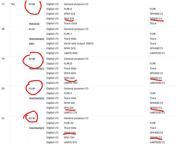
How to implement two sets of SPI on the NCS v3.0.0 nRF54L15 P2 port? If it can be achieved, please provide the corresponding IO ports for these two sets of SPI.

Kind regards,
Peter.Min

Parents
  • Hi Peter

    You can follow the pin assignments "dedicated function" tab in p.841-843. 

    For reference, you can use the following config with for example SPIM20 and SPIM21:

    SPIM20:

    CS -    P2.00
    CLK -  P2.01
    SDO - P2.02
    SDI -   P2.04

    SPIM21:

    CS -    P2.10
    CLK -  P2.06
    SDO - P2.08
    SDI -   P2.09

    Best regards,

    Simon

  • Hello Simon,

    Could you please review the latest post under this private ticket  (Missing Ticket) 

    359159

    In particular, the question about your recommended SPIM21 configuration NOT working in BLE companion configuration

    SPIM21:

    CS -    P2.10
    CLK -  P2.06
    SDO - P2.08
    SDI -   P2.09

    Could you please explain from the https://docs.nordicsemi.com/bundle/ps_nrf54L15/page/chapters/pin.html

    which exact section would explain why the above recommendation would NOT work?

    Thank you and kind regards,

    Jamal

  • Hello Simon,

    Should I create a new separate ticket to raise the same question?

    Thank you and kind regards,

    Jamal


  • Hi

    We don't get notifications on "Verified" answer tickets, so I didn't see this until you tagged me. Sorry about that. If you're working on a DK, some of these pins are used for other things by default, so that's the most likely reason this doesn't work by default. On the back of the nRF54L15 DK you can see that P2.09 for example is used for one of the onboard LEDs, so you need to make sure it isn't configured for the LED in your project.

    Best regards,

    Simon

  • Hi  ,

    Understood about the notification system.

    Thanks for the feedback.

    I believe there are other reason(s) pins from the P2 board are not working.

    And that's what I am trying to understand....

    For solving pin conflict on the L15DK, I already have the following added to my .overlay

    /delete-node/ &button1;
    /delete-node/ &button2;
    /delete-node/ &led0;
    /delete-node/ &led2;

    According to  :

    There is some restriction to use pins on nRF54L15 based on the power domain. 

    You can read this pin assignment chapter Pin assignments also to know about the pin mapping on nRF54L15.

    However, I could not figure out which exact section of that document offer specifics about those restrictions.

    Things are working fine on the DKs environment for now.

    But when we move to our custom design schematics, we will have to make sure we are in line with those recommendations / restrictions.

    Thank you and kind regards,

    Jamal

Reply
  • Hi  ,

    Understood about the notification system.

    Thanks for the feedback.

    I believe there are other reason(s) pins from the P2 board are not working.

    And that's what I am trying to understand....

    For solving pin conflict on the L15DK, I already have the following added to my .overlay

    /delete-node/ &button1;
    /delete-node/ &button2;
    /delete-node/ &led0;
    /delete-node/ &led2;

    According to  :

    There is some restriction to use pins on nRF54L15 based on the power domain. 

    You can read this pin assignment chapter Pin assignments also to know about the pin mapping on nRF54L15.

    However, I could not figure out which exact section of that document offer specifics about those restrictions.

    Things are working fine on the DKs environment for now.

    But when we move to our custom design schematics, we will have to make sure we are in line with those recommendations / restrictions.

    Thank you and kind regards,

    Jamal

Children
No Data
Related