My nRF52840 Module keeps resetting after I changing the mode to LDO

Hi.

I made the smallest system module using nRF52840. The schematic diagram is as follows.

My reference design for power supply is as follows,

For Firmware.

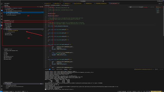
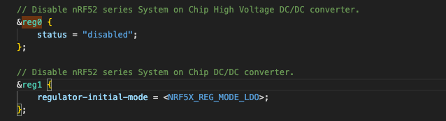
I copied the routine nRF Desktop in nRF Connect SDK V3.0.2 for test and added the following code to switch internal power supply to LDO in app.overlay.

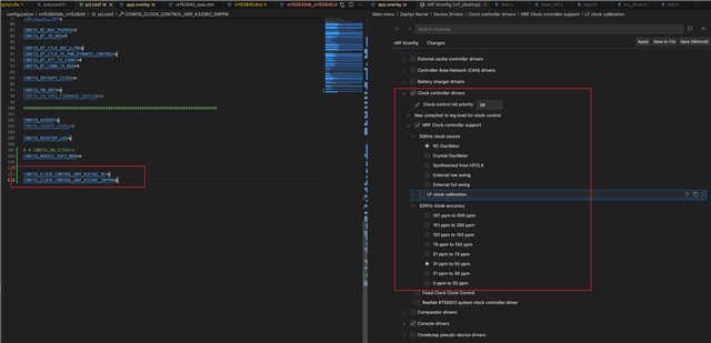
At the same time I added the following code for test in the same file.

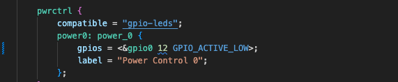
My module looks like keeps resetting after I burn the firmware, according to the waveform of P0.12.

May I ask how I can make the routine run normally on my module?

Parents
  • Hi,

    I could see the following issues in your schematic:

    1. This capacitor is not required here:

    2. The components and values in your ANT section is very different from our reference, which is:

    We recommend following it exactly for guaranteed performance.

    3. This is N.C in the reference:

    4. Are you using the USB? If yes, you need to connect 4.7uF to ground from the VBUS pin and if not using, then you need to directly ground the VBUS pin.

    5. Please make sure you have chosen the crystal caps accordng to the crystal frequencies:

    Regards,

    Priyanka

  • Hi,

    I took some time to do some tests based on all your suggestions. But it still not normal.

    So I reconfirmed the differences between my main board and the development board in the schematic diagram.

    I find the difference is my main board doesn't have 32.768kHz RC oscillator(LFRC).

    So I reconfigured my project with adding following setting 

    Of course, it doesn't have QSPI Nor Flash, so I disabled QSPI Nor Flash too。

    Until now, it can run in Debug mode, but still blocked in full speed running mode.

    It seems to be related to correct configuration of LFRC. Is my configuration the correct one?

    By the way, no matter how I add configuration to the project it still can run on nRF52840DK board.

  • I guess maybe the issue is you enabling:

    CONFIG_CLOCK_CONTROL_NRF_K32SRC_RC=y
    CONFIG_CLOCK_CONTROL_NRF_K32SRC_50PPM=y

    These configs assume that you have an LFRC or crystal. So maybe you could try to use:
    CONFIG_CLOCK_CONTROL_NRF_K32SRC_SYNTH=y
    CONFIG_CLOCK_CONTROL_NRF_K32SRC_RC=n
    CONFIG_CLOCK_CONTROL_NRF_K32SRC_XTAL=n

    This is LFCLK which is synthesized from the HFCLK. Also, disable caliberation as it migh require an actual LFCLK:

    CONFIG_CLOCK_CONTROL_NRF_CALIBRATION=n

    Regards,

    Priyanka

Reply
  • I guess maybe the issue is you enabling:

    CONFIG_CLOCK_CONTROL_NRF_K32SRC_RC=y
    CONFIG_CLOCK_CONTROL_NRF_K32SRC_50PPM=y

    These configs assume that you have an LFRC or crystal. So maybe you could try to use:
    CONFIG_CLOCK_CONTROL_NRF_K32SRC_SYNTH=y
    CONFIG_CLOCK_CONTROL_NRF_K32SRC_RC=n
    CONFIG_CLOCK_CONTROL_NRF_K32SRC_XTAL=n

    This is LFCLK which is synthesized from the HFCLK. Also, disable caliberation as it migh require an actual LFCLK:

    CONFIG_CLOCK_CONTROL_NRF_CALIBRATION=n

    Regards,

    Priyanka

Children
  • I found such a graph from the data sheet. The red box should be the configuration you suggested, and the blue box is my previous configuration. I had test both two configurations. They have the same result.

    I discovered a new phenomenon in the process of testing.

    1. When I physically connected the debugger and the board and powered on, I couldn't search for the Bluetooth device. At this point, even if the board can be connected to JLink RTT Viewer, there will be no debug information output

    1. When I use the JLink RTT Viewer and connect to the board, after short-circuiting the RESET pin and GND to reset the board, I can search for the Bluetooth device. At this point, after reconnecting the board with RTT Viewer, debugging information will be output.

    I found several similar issues in the Dev Zone and follow their solution to reconfigure my project. but still not work on my issue.

    The most similar issues link is as follow:

    https://devzone.nordicsemi.com/f/nordic-q-a/120786/nrf52810-board-will-not-start-on-its-own-it-needs-the-rtt-viewer-to-be-connected-then-it-will-start-and-run/538530

    But I have confirmed my configurations. It’s already configure to LDO.

    Now I don’t know how to solve this issues。

    Please give me some guidance.

  • OK! I finally found the point in this issues.

    #1 has three items in the project and nrf_desktop include app.overlay, s1_image also include it. But b0 dosn’t include app.overlay. You can see it in follow picture. (#2 hasn’t include app.overlay)

    So this project will block in b0 because b0 is set to DCDC. My board is used LDO.

    I wrote the regulator configure code as follow in the file nrf52840dk_nrf52840.dts which is included by three items in #1.

    Now my board can run without connect to the debugger.

Related