
Good evening. We're running into an issue with using all 4 peripherals on the nRF9151. At the moment we are using the 9151DK.
The issue arises as soon as we enable spi1 (or any other peripheral1) we get the following boot loop:
*** Booting MCUboot v2.1.0-dev-ae1ee57f3906 ***
*** Using nRF Connect SDK v3.0.2-89ba1294ac9b ***
*** Using Zephyr OS v4.0.99-f791c49f492c ***
I: Starting bootloader
I: Primary image: magic=unset, swap_type=0x1, copy_done=0x3, image_ok=0x3
I: Secondary image: magic=unset, swap_type=0x1, copy_done=0x3, image_ok=0x3
I: Boot source: none
I: Image index: 0, Swap type: none
I: Bootloader chainload address offset: 0x10000
I: Image version: v0.0.0
�E: ***** BUS FAULT *****mage slot
E:   Precise data bus error
E:   BFAR Address: 0x0
E: r0/a1:  0x00056244  r1/a2:  0x00055e40  r2/a3:  0x00033998
E: r3/a4:  0x40009000 r12/ip:  0x00000000 r14/lr:  0x0004d3c3
E:  xpsr:  0x81000000
E: Faulting instruction address (r15/pc): 0x00033a30
E: >>> ZEPHYR FATAL ERROR 25: Unknown error on CPU 0
E: Current thread: 0x2000e310 (main)
We are using spi3 for the gd25wb256 flash, uart0 for logging, i2c2 for a battery management IC and we need would like to use spi1 for ads124s08 ADC.
Swapping I2C2 to I2C1 and SPI1 to SPI2, Disabling I2C2 but keeping SPI1 keeps BUS FAULT.
This is not caused by any part of code as even a hello world program would exhibit the same issue with this config:
prj.conf:
#
# Copyright (c) 2019 Nordic Semiconductor ASA
#
# SPDX-License-Identifier: LicenseRef-Nordic-5-Clause
#
# General config
CONFIG_NCS_SAMPLES_DEFAULTS=y
CONFIG_REBOOT=y
CONFIG_NEWLIB_LIBC=y

# Network
CONFIG_NETWORKING=y
CONFIG_NET_SOCKETS=y
CONFIG_NET_NATIVE=y
CONFIG_NET_IPV4=y
CONFIG_NET_TCP=y
CONFIG_NET_UDP=y
CONFIG_DNS_RESOLVER=y

# Sockets
CONFIG_ZVFS_POLL_MAX=4
CONFIG_POSIX_API=y
CONFIG_POSIX_TIMERS=y

# Network driver config
CONFIG_TEST_RANDOM_GENERATOR=y

# Network buffers
CONFIG_NET_PKT_RX_COUNT=16
CONFIG_NET_PKT_TX_COUNT=16
CONFIG_NET_BUF_RX_COUNT=128
CONFIG_NET_BUF_TX_COUNT=128
CONFIG_NET_CONTEXT_NET_PKT_POOL=y

# LTE link control
CONFIG_LTE_LINK_CONTROL=y

# Modem library
CONFIG_NRF_MODEM_LIB=y
CONFIG_MODEM_INFO=y

# Shell configurations
CONFIG_SHELL=y
CONFIG_SHELL_WILDCARD=n
CONFIG_SHELL_CMD_BUFF_SIZE=128

# HTTP
CONFIG_HTTP_CLIENT=y

# TLS
CONFIG_NRF_SECURITY=y
CONFIG_MBEDTLS=y
CONFIG_TLS_CREDENTIALS=y
CONFIG_NET_SOCKETS_OFFLOAD=y
CONFIG_MBEDTLS_ENABLE_HEAP=y
CONFIG_MBEDTLS_HEAP_SIZE=16384
CONFIG_MBEDTLS_LEGACY_CRYPTO_C=y


# Library for buttons and LEDs
CONFIG_DK_LIBRARY=y

# Heap and stacks
CONFIG_HEAP_MEM_POOL_SIZE=2048
CONFIG_MAIN_STACK_SIZE=8192
CONFIG_SYSTEM_WORKQUEUE_STACK_SIZE=2048

# Image manager
CONFIG_IMG_MANAGER=y
CONFIG_FLASH=y
CONFIG_FLASH_MAP=y
CONFIG_STREAM_FLASH=y
CONFIG_IMG_ERASE_PROGRESSIVELY=y

# GPIO
CONFIG_GPIO=y

# FOTA library
CONFIG_FOTA_DOWNLOAD=y

# Download client
CONFIG_DOWNLOADER=y
CONFIG_DOWNLOADER_STACK_SIZE=4096

# DFU Target
CONFIG_DFU_TARGET=y

# Modem key management
CONFIG_MODEM_KEY_MGMT=y

# Application Upgrade support
CONFIG_BOOTLOADER_MCUBOOT=y

# logging
CONFIG_LOG=y
CONFIG_NET_LOG=y
CONFIG_NET_SOCKETS_LOG_LEVEL_DBG=n
CONFIG_NET_HTTP_LOG_LEVEL_DBG=n
CONFIG_NET_IPV6_LOG_LEVEL_DBG=n
CONFIG_NET_IPV6_ND_LOG_LEVEL_DBG=n
CONFIG_CBPRINTF_FP_SUPPORT=y


# Put MCUboot’s secondary slot in that external region
CONFIG_GPIO=y
CONFIG_SPI=y
CONFIG_SPI_NOR=y
CONFIG_SPI_NOR_SFDP_DEVICETREE=y
CONFIG_SPI_NOR_FLASH_LAYOUT_PAGE_SIZE=4096
CONFIG_NORDIC_QSPI_NOR=n

# i2c
CONFIG_I2C=y
APP overlay file:
// To get started, press Ctrl+Space to bring up the completion menu and view the available nodes.

// You can also use the buttons in the sidebar to perform actions on nodes.
// Actions currently available include:

// * Enabling / disabling the node
// * Adding the bus to a bus
// * Removing the node
// * Connecting ADC channels

// For more help, browse the DeviceTree documentation at https://docs.zephyrproject.org/latest/guides/dts/index.html
// You can also visit the nRF DeviceTree extension documentation at https://docs.nordicsemi.com/bundle/nrf-connect-vscode/page/guides/ncs_configure_app.html#devicetree-support-in-the-extension

&gd25wb256 {
	status = "okay";
};

&spi3 {
    status = "okay";
};
/ {

    chosen {
        nordic,pm-ext-flash = &gd25wb256;
    };

    zephyr,user {
        ads124s08_drdy_gpio-gpios = <&gpio0 2 0>;
        ads124s08_start_gpio-gpios = <&gpio0 3 0>;
    };
};


&pinctrl {


    spi1_default: spi1_default {
        group1 {
            psels = <NRF_PSEL(SPIM_SCK, 0, 4)>,
                    <NRF_PSEL(SPIM_MOSI, 0, 5)>,
                    <NRF_PSEL(SPIM_MISO, 0, 6)>;
        };
    };
    spi1_sleep: spi1_sleep {
        group1 {
            psels = <NRF_PSEL(SPIM_SCK, 0, 4)>,
                    <NRF_PSEL(SPIM_MOSI, 0, 5)>,
                    <NRF_PSEL(SPIM_MISO, 0, 6)>;
        };
    };
};
&i2c2 {
    status = "disabled";
    clock-frequency = <I2C_BITRATE_STANDARD>;
    pinctrl-0 = <&i2c2_default>;
    pinctrl-1 = <&i2c2_sleep>;
    pinctrl-names = "default", "sleep";

    bq40z50: bq40z50@0b {
        status = "okay";
        compatible = "i2c-device";
        reg = <0x0b>;
        label = "bq40z50";
    };
};

&spi1 {
    status = "okay";
    cs-gpios = <&gpio0 1 0>;
    pinctrl-0 = <&spi1_default>;
    pinctrl-1 = <&spi1_sleep>;
    pinctrl-names = "default", "sleep";
    ads124s08: ads124s08@0 {
        status = "okay";
        compatible = "spi-device";
        spi-max-frequency = <2000000>;
        reg = <0x0>;
    };
};

&led0 {
    status = "disabled";
};

&led1 {
    status = "disabled";
};

&led2 {
    status = "disabled";
};

&led3 {
    status = "disabled";
};
MCUBOOT.conf:
CONFIG_GPIO=y
CONFIG_SPI=y
CONFIG_SPI_NOR=y
CONFIG_SPI_NOR_SFDP_DEVICETREE=y
CONFIG_SPI_NOR_FLASH_LAYOUT_PAGE_SIZE=4096
CONFIG_NORDIC_QSPI_NOR=n  # required by SPI driver
CONFIG_MULTITHREADING=y
CONFIG_BOOT_MAX_IMG_SECTORS=512
MCUBOOT overlay:
&gd25wb256 {
    status = "okay";
};
/ {
    chosen {
        nordic,pm-ext-flash = &gd25wb256;
    };
};
Analysing the exact moment of the crash:
- crash happens (presumably) after MCUBOOT on pinctrl_nrf.c at "pinctrl_configure_pins" function, specifically, this line "NRF_PSEL_SPIM(reg, SCK) = psel;"
- it is caused by setting the SCK pin (at the time we used pin 22)
- I made the breakpoint conditional (for the function) when the reg parameter is (0x40009000) which is for SPI1.
- This made it possible to step into the code (without it, the debugger would crash as soon as you step into it)
- reg is 0x40009000 which is indeed for SPI1 (or any "1" peripherial)
- the pin count is 3 (mosi, miso, sck) as we expect
- the *pins is 0x5623c or "0101 0110 0010 0011 1100" in binary
- Stepping into that line goes to the fault we expect.
- This happens in the first loop iterarion on the SCK pin (22)
- As soon as you go into that macro, we get this:
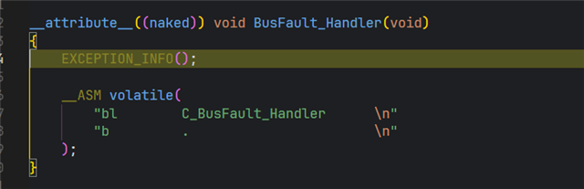
- debugger on the moment of the crash
Are we doing something seriously wrong or it is not possible to use all 4 peripherals at once?
Thanks so much in advance for any guidance or input.
-AA

