For our custom nrf9151 board,
The following is the prj.conf:
CONFIG_SERIAL=n
CONFIG_UART_CONSOLE=n
CONFIG_LOG=n
CONFIG_LOG_BACKEND_RTT=n
CONFIG_LOG_BACKEND_UART=n

CONFIG_NRF_MODEM_LIB=n
CONFIG_NETWORKING=n
CONFIG_I2C=n
CONFIG_ADC=n
CONFIG_CBPRINTF_FP_SUPPORT=n
CONFIG_INPUT=n
CONFIG_PWM=n
CONFIG_PWM_NRFX=n

CONFIG_NVS=n
CONFIG_FLASH=n
There are no pullups on any GPIO and for now, assume there are no peripherals connected,
but there is a flash chip W25Q32JVZPIQ with the following pinout:
WP: 11
DI: 10
CLK: 9
RST: 8
DO:12
CS: 13
The following is called in main:
static const struct device *const port0 = DEVICE_DT_GET(DT_NODELABEL(gpio0));


ret = gpio_pin_configure(port0, 0, GPIO_OUTPUT_LOW );
ret = gpio_pin_configure(port0, 1, GPIO_OUTPUT_LOW );
ret = gpio_pin_configure(port0, 2, GPIO_OUTPUT_LOW );
ret = gpio_pin_configure(port0, 3, GPIO_OUTPUT_LOW );
ret = gpio_pin_configure(port0, 4, GPIO_OUTPUT_LOW );
ret = gpio_pin_configure(port0, 5, GPIO_OUTPUT_LOW );

ret = gpio_pin_configure(port0, 6, GPIO_OUTPUT_LOW );
ret = gpio_pin_configure(port0, 7, GPIO_OUTPUT_LOW );

ret = gpio_pin_configure(port0, 8, GPIO_OUTPUT_LOW );
ret = gpio_pin_configure(port0, 9, GPIO_OUTPUT_LOW );
ret = gpio_pin_configure(port0, 10, GPIO_OUTPUT_LOW );
ret = gpio_pin_configure(port0, 11, GPIO_OUTPUT_LOW );
ret = gpio_pin_configure(port0, 12, GPIO_OUTPUT_LOW );

ret = gpio_pin_configure(port0, 13, GPIO_OUTPUT_LOW );

ret = gpio_pin_configure(port0, 14, GPIO_OUTPUT_LOW );
ret = gpio_pin_configure(port0, 15, GPIO_OUTPUT_LOW );
ret = gpio_pin_configure(port0, 16, GPIO_OUTPUT_LOW );

ret = gpio_pin_configure(port0, 17, GPIO_OUTPUT_LOW );
ret = gpio_pin_configure(port0, 18, GPIO_OUTPUT_LOW );
ret = gpio_pin_configure(port0, 19, GPIO_OUTPUT_LOW );
ret = gpio_pin_configure(port0, 20, GPIO_OUTPUT_LOW );

ret = gpio_pin_configure(port0, 21, GPIO_OUTPUT_LOW );


ret = gpio_pin_configure(port0, 22, GPIO_OUTPUT_LOW );
ret = gpio_pin_configure(port0, 23, GPIO_OUTPUT_LOW );
ret = gpio_pin_configure(port0, 24, GPIO_OUTPUT_LOW );
ret = gpio_pin_configure(port0, 25, GPIO_OUTPUT_LOW );

ret = gpio_pin_configure(port0, 26, GPIO_OUTPUT_LOW );
ret = gpio_pin_configure(port0, 27, GPIO_OUTPUT_LOW );

ret = gpio_pin_configure(port0, 29, GPIO_OUTPUT_LOW );

ret = gpio_pin_configure(port0, 30, GPIO_OUTPUT_LOW );
ret = gpio_pin_configure(port0, 31, GPIO_OUTPUT_LOW );

NRF_REGULATORS->SYSTEMOFF = 1;
Essentially, all pins are pulled LOW and SYSTEM_OFF is invoked.
For some strange reason, I can see a current draw of 3.5mA !
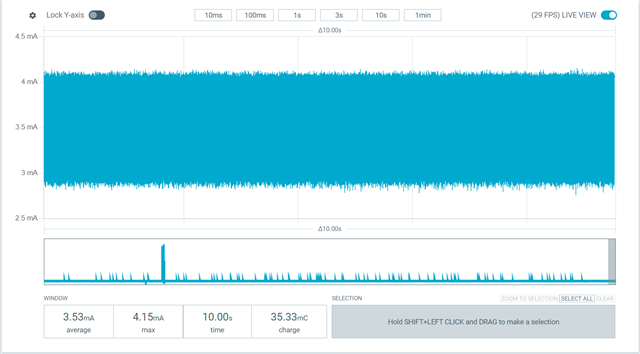
What am I missing?
How do I test a low power scenario for my board?
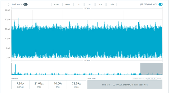
How do I reach 2.2uA?
IMCUON1 | MCU on IDLE, modem off, RTC on | 2.2 µA
as described in:
https://docs.nordicsemi.com/bundle/ps_nrf9151/page/_tmp/alta.nRF9151/autodita/APPLICATION.CURRENT/parameters.id_current_sleep.html