Required components NRF54L15

Dear reader,

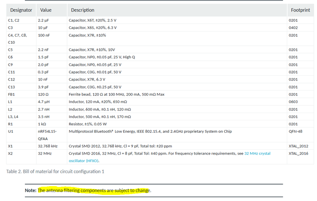
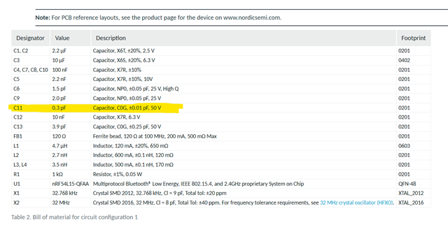
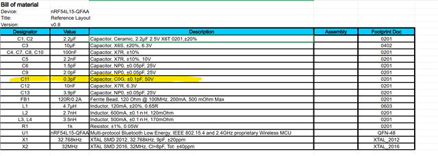
I am currently working on a project involving the NRF54L15 microcontroller. In the specifications of the MCU, under Circuit Configuration 1 for QFN48 (QFAA), there is a list of all the required components.

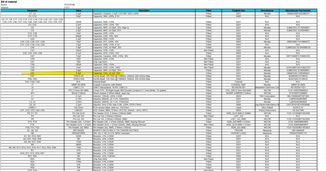
While searching for these components, I ran into some difficulties, as I wasn’t able to find several components that matched the required specifications. To address this, I looked into the BOM file of the NRF54L15 DK to see which components were used there.

However, I noticed that nearly all components used on the DK board do not match the requirements listed in the Circuit Configuration components list.

Would it be better for me to search for components that match the specification list as closely as possible, or should I stick to the components used on the DK board?

I look forward to your clarification.

Kind regards,

James

Parents
  • Hi,

    Use the latest reference HW files available from the product page if possible but you can also use the DK as a reference, but make sure you have the latest DK version. 
    https://www.nordicsemi.com/Products/nRF54L15/Reference-layout?lang=en#infotabs 
    Sometimes one can be a bit ahead of the other. 


    From https://docs.nordicsemi.com/bundle/ps_nrf54L15/page/chapters/ref_circuitry.html#ariaid-title2 

    Is this the list you reference where you see discrepancies?

    Regards,
    Jonathan

  • Hi Jonathan,

    First of all, thank you for your response. I have indeed looked at the website you linked, and from that link, I downloaded the documentation for the DK board: nRF54L15 DK

    I also just downloaded the documentation file you linked for the standalone NRF54L15 and noticed a difference. Highlighted in the documentation from the DevZone website, for C11, it specifies: 0.3 pF, Capacitor, C0G, ±0.01 pF, 50 V. However, in the XLS file from the download link, as well as in the DK board's BOM file, it states a tolerance of ±0.1 pF.
    From this, I assume that the correct tolerance to use is ±0.1 pF.

    Additionally, I noticed something else: in the downloadable documentation from Nordic for the standalone NRF54L15 (which you also referred to above), there is no BOM file included. I was, however, able to find one in the DK board documentation. Based on my research, most of the components meet the stated requirements. However, one thing stood out to me:
    In all three documents — both XLS files and the DevZone website — the requirements for C1 and C2 are listed as:
    2.2µF Capacitor, Ceramic, 2.2µF 2.5V X6T 0201, ±20%.

    I searched for a matching component and found GRM033D80E225ME47D , which, to my knowledge, fully meets these specifications.
    However, since I couldn't find a capacitor with the ±0.01 pF tolerance for C11, I looked into the BOM file from the DK board. There, I noticed that for C1 and C2, the component used is GRM033R61A225KE47D  — an X5R, 10VDC, 10% tolerance component, which does not align with the stated requirements.

    At this point, I’m unsure whether I should be sourcing components that match the requirements as closely as possible myself, or whether I should simply adopt the components listed in the DK board BOM.
    As for C11, I’m assuming that the ±0.01 pF tolerance is a typo and that it should actually be ±0.1 pF.

    I would appreciate your response and any advice or corrections if needed.

    Best regards, and thank you in advance,
    James

Reply
  • Hi Jonathan,

    First of all, thank you for your response. I have indeed looked at the website you linked, and from that link, I downloaded the documentation for the DK board: nRF54L15 DK

    I also just downloaded the documentation file you linked for the standalone NRF54L15 and noticed a difference. Highlighted in the documentation from the DevZone website, for C11, it specifies: 0.3 pF, Capacitor, C0G, ±0.01 pF, 50 V. However, in the XLS file from the download link, as well as in the DK board's BOM file, it states a tolerance of ±0.1 pF.
    From this, I assume that the correct tolerance to use is ±0.1 pF.

    Additionally, I noticed something else: in the downloadable documentation from Nordic for the standalone NRF54L15 (which you also referred to above), there is no BOM file included. I was, however, able to find one in the DK board documentation. Based on my research, most of the components meet the stated requirements. However, one thing stood out to me:
    In all three documents — both XLS files and the DevZone website — the requirements for C1 and C2 are listed as:
    2.2µF Capacitor, Ceramic, 2.2µF 2.5V X6T 0201, ±20%.

    I searched for a matching component and found GRM033D80E225ME47D , which, to my knowledge, fully meets these specifications.
    However, since I couldn't find a capacitor with the ±0.01 pF tolerance for C11, I looked into the BOM file from the DK board. There, I noticed that for C1 and C2, the component used is GRM033R61A225KE47D  — an X5R, 10VDC, 10% tolerance component, which does not align with the stated requirements.

    At this point, I’m unsure whether I should be sourcing components that match the requirements as closely as possible myself, or whether I should simply adopt the components listed in the DK board BOM.
    As for C11, I’m assuming that the ±0.01 pF tolerance is a typo and that it should actually be ±0.1 pF.

    I would appreciate your response and any advice or corrections if needed.

    Best regards, and thank you in advance,
    James

Children
Related