nRF54L15 - System OFF : strange current peaks

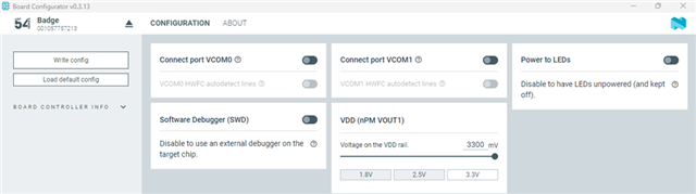
I'm working with the nRF54L15-dk and with the system OFF sample available in https://docs.nordicsemi.com/bundle/ncs-latest/page/zephyr/samples/boards/nordic/system_off/README.html with SDK ver 3.0.2.

Following this post :  abnormal current peak when system off (0.6mA) 

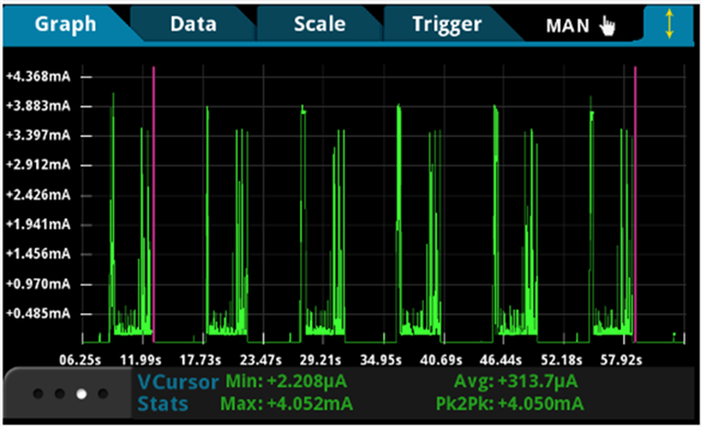
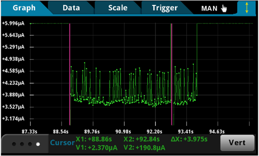
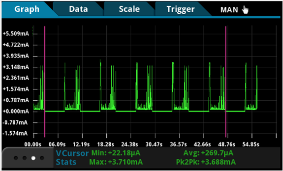
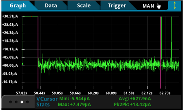
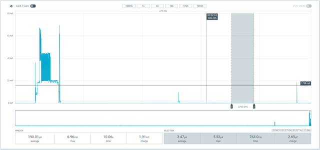
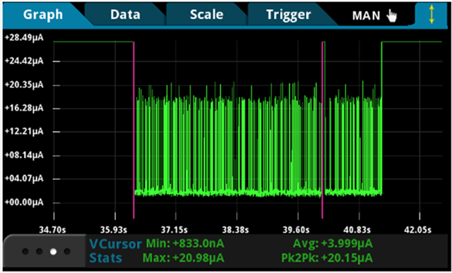
I measured the current with a digit multimeter DMM7510 on the P6 header on the dev kit. With either the wake on pin (GPIO interrupt) or the GRTC wake up (period = 10 s), I'm seeing those strange current peaks after about 3-4 seconds. I run the program without RAM retention.

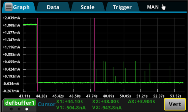
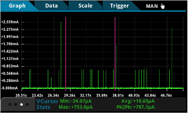
They appear irregularly and seem to be cap at about 750 µA. 

What could be the cause of those peaks and how to get rid to them ? 

Best regards, 

Patrick

Parents
  • Hi,


    It is expected that you see a spike due to how the regulators behave in low power mode.

    I do not know what your multimeters sampling rate is, but this can cause aliasing if the sampling freq is too low.


    Is the overall measurement as expected?


    Kind regards,

    Håkon

  • Hello, 

    I see. We can't to realy much about it, right ?
    I used 0.01 NPLC on my multimeter. So I don't think there would be some aliasing problems. 

    Yes the overall measurement is a bit higher than the datasheet but it's ok.

    I have another issue with the system ON mode when the chip is idle. 


    With my custom board

    With the nRF54L15-dk

    So when the device in on idle mode with system ON (2nd picture zoomed in), without any RAM retention or GRTC/GPIO to wake up, there are some peaks that appear regularly every 4 seconds. 
    I found that it is caused by the RC oscillator calibration which happens by default every 4 seconds. Because, my pictures were taken on a custom board that doesn't include the LFXO, only the RC oscillator. So, maybe the nRF54L15-dk is using that LFXO oscillator to go into sleep mode and doesn't need to activate the RC oscillato hence no current peak on that period of sleep. 
    I couldn't find any way to get rid of those peaks or to delay that calibration since the old answer were not on the nRF54L15 or an older version of nRF Connect SDK. 

    Do you have any clue if it is possible to reduce those peaks ?

    Thanks and best regards,

    Patrick

  • Hello Håkon, 

    I did my current measurement for the system off and I'm getting this : 

    What do you measure then?

    So it follows effectively what the datasheet describles.

    But I still can't get the system ON current to be as low as about 3.7 uA since it's the maximum when using the RC oscillator if I understand the table correctly, with my config. 

    Best regards,

    Patrick

  • Hi Patrick,


    I noticed, when testing, that there's a leakage from the LED net. Can you ensure that the LED0/LED1/LED2/LED3 pins are floating when testing?

    I noticed that I get ~6 uA when the LED0 GPIO is configured as output (LED = inactive), and this disappears when reconfiguring the pin to inactive/floating state.


    Kind regards,

    Håkon

  • Hi Håkon, 

    How can I put my leds into a floating state ? Because, I've already set the power to LEDs off as you can see in my picture below. So is it still not enough then ? 

    I may only want to disable them in the system ON phase so I can use them otherwise ? Is there a function that can help me doing so ? 

    Thanks and best regards, 

    Patrick

  • Hi Patrick,


    It was in case you have any of the pins set as output in your test fw.

    You need to check the base current of your implementation, as the fw will wake up every x seconds to calibrate your RC oscillator. You need to measure the current "in between" to compare against the number in the datasheet:


    The above is from blinky (w/CONFIG_SERIAL=n and CONFIG_CLOCK_CONTROL_NRF_K32SRC_RC=y), where I removed the whole main, and just returned.


    Kind regards,

    Håkon

  • Hello Håkon, 

    so I've tried measuring the in between peak current on my program with my custom board and I'm getting this value : 

    It's 1 uA below the average current if I take the whole 5 secondes. 

    In my program, I'm only using two LEDs and the other are not defined in my custom board so it shouldn't matter I think.
    You still haven't told me how to disable them by passing them in the floating state in my program before I enter into the system ON sleep.

    Best regards, 

    Patrick

Reply
  • Hello Håkon, 

    so I've tried measuring the in between peak current on my program with my custom board and I'm getting this value : 

    It's 1 uA below the average current if I take the whole 5 secondes. 

    In my program, I'm only using two LEDs and the other are not defined in my custom board so it shouldn't matter I think.
    You still haven't told me how to disable them by passing them in the floating state in my program before I enter into the system ON sleep.

    Best regards, 

    Patrick

Children
Related