nRF54L15-DK suspiciously high sleep current

Greetings to everybody!

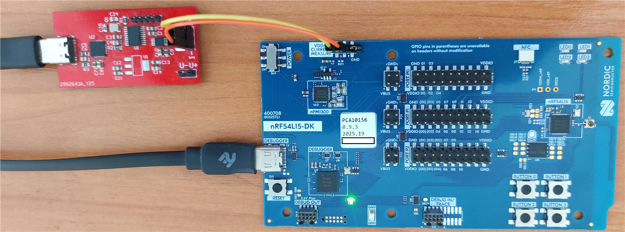
There is some question about nRF54L15-DK board measured current consumption.
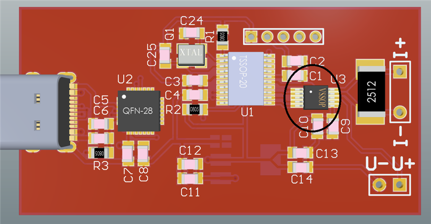
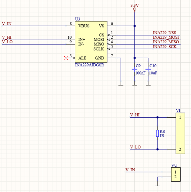
I measure current via the P6 connector, that is, I measure current within the VDDM_nRF cirquit.
Which is precisely the nRF54L15's MCU consumption. This goes to pin 48 (VDD). While the rest VDD pins (47, 10, 22, 36) are named VDD_nRF
and used to derive the VDDIO voltage (as well as VDD_DBGR) via the NPN-Transistor/OA buffer. So, VDDIO is actually drawn from the +5V VBUS, not from the VDD_nRF. VDD_nRF is used solely as a reference level.
The board has QSPI flash chip, but it is powered from VDDIO line, thus no consumption influence inside the measured cirquit (VDDM_nRF). Same with LEDs - those are outside the VDDM_nRF power domain.

I have Nordic nRF Connect SDK v.3.0.2 installed (in c:\ncs folder). I use SystemInit() from the system_nrf54l.c file ("c:\ncs\v3.0.2\modules\hal\nordic\nrfx\mdk\system_nrf54l.c")

I have created a simple IAR project which contains the main.c file with almost empty main function, the system_nrf54l.c is addded to the IAR project tree. 
In the IAR's Project Options/C++ Compiler/Defined Symbols I defined minimum required things required for nordic's nrf.h and system_nrf54l.c to recognize nRF54L15's Cortex-M33 core correctly.
(like NRF54L15_XXAA and __ARM_FEATURE_CMSE)


In startup.s file I call "bl SystemInit" - so the very first instruction after reset calls the SystemInit, which in its turn, the official Nordic startup code.
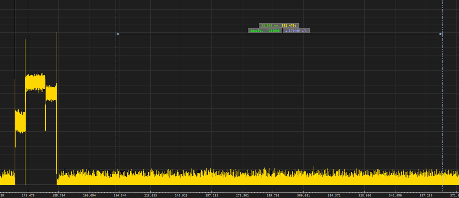
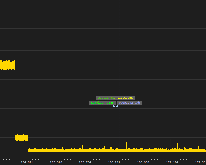
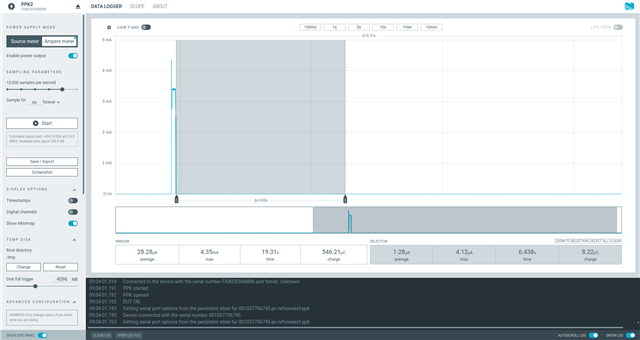
This code initializes clocks, enables Debug AP, turns on DCDC. Without SystemInit(), the current consumption is about 820uA. Right after the DCDC is enabled inside the SystemInit(), the current drops to ~35uA.


Then the main() function is finally called and there I just have:

  while (true)
  {
    SCB->SCR |= SCB_SCR_SLEEPDEEP_Msk;
    __WFE();
  }
 
 System definitely stays in the sleep mode. After reset no peripherals are touched, since this is uber simple IAR project, it just goes to main after SystemInit().
 But no matter what I do, I have 35 uA consumption. I would expect in sleep mode current to drop to about 1-2 uA.
 
 I would like again to stress out the fact that this is the IAR ARM project, it is uber simple, it is not zephyr compiled project. In IAR project I'm 100% sure that after reset,
 the MCU just executes SystemInit() and then goes into main(). Thus no hidden or forgotten code which could init or power some power domain which could be the reason of 35uA consumption.

The asm startup code is this:

......

pubweak Reset_Handler
section .text:CODE:REORDER:NOROOT(2)
        
Reset_Handler
  bl SystemInit
  b __iar_program_start

......


 Maybe MCU after reset and Nordic's SystemInit() still has some powered peripheral which needs to be shut down? But what this could be, since I'd expect after reset MCU is in its less used power state.


 Please suggest where could be the problem?

Parents
  • Hi,


    Can you share a picture of how you measure current?

    Have you tried the system off sample that we have in the SDK? https://github.com/nrfconnect/sdk-zephyr/tree/main/samples/boards/nordic/system_off


    When using the DK, it is important that you follow the prerequisites here:

    https://docs.nordicsemi.com/bundle/ug_nrf54l15_dk/page/UG/nRF54L15_DK/measurements/set_up_dk.html


    Kind regards,

    Håkon

  • Hi,

    here is the screenshot of my current measurement software - the measurement was done for the system_off sample from

    ..\sdk-zephyr-main\samples\boards\nordic\system_off. Consumption looks the same, about 32.4 uA – like the one I measure on my test firmware I described in the previous posts - when shutting off memory (NRF_MEMCONF->POWER[i].CONTROL = 0x00) for SYSTEM OFF mode.

    The next picture just shows a zoomed-in part of graph, to show the DC/DC in action – the spikes are at about 110ms distance – those are suck-ups by DC/DC, it is expected. But still, the average current is about 32.5uA

    On next two pictures is my actual setup for the current measurement. I use custom made current measurement board as well as software, developed by me, which receives samples from the measurement PCB and draws graphs, makes average current calculations, etc.

    The sensor element used is the INA229 chip. So, current goes though the shunt resistor, and voltage drop is measured by the INA229 chip. The PCB on photo has 3 Ohm shunt resistor installed.

    To be clear, here is the part of the current sensing schematics of the above mentioned device (though on schematics there is 1 Ohm shunt specified, never mind it):

    This setup I use for more than a year on other projects, and it is proved functional. For example, I also tested the ProMicro PCB (the cheap device, can be found on aliexpress) - based on the Nordic nRF52840. Having removed the LDO chip from that PCB (since it draws few uA itself), I power that PCB from an external 3.6V battery and measure 1-2 uA when chip is in sleep mode, which is totally in sync with the specifications.

    But here, on nRF54L15DK, as I've already said, current is 32-35 uA. I have even excluded the possibility of some really exotic case (but on such stage of research for the problem, one already starts blowing on the water) like taking into account, that board is powered from USB port from the same domain as my current measurement board (which is also attached to USB), so if there are some side currents flowing... I don't know. Anyway, I disconnected USB cable from the nRF54L15DK and attached a 4.2V Li-Ion battery as the power source instead - thus now it is 100% standalone operation of the board.

    But, results are totally same as before - the consumption graph in this case is not influenced at all, looks exactly like the one  from the very first picture here, and same 32-35 uA in sleep mode (32uA if I shutdown memory in system off mode and 35 uA if I leave it on default settings)


    P.S. Also, as to the second link - about prerequisites for setting up the DK for current measurements - there are two advises like "Consider disconnecting the virtual serial port connections..." - which is kinda not clear to me how those can influence, since those analog switches are powered from the VDD_DBGR power domain, which in its turn is derived from transitor buffer, and does not belong to the VDDM_nRF domain. Whatever state of nRF5340's VCOM pins/ports is irrelevant, since nRF54L15 after reset has all GPIOs disconnected and I don't see how this can increase sleep current up to 32-35uA. But ok, I tested in JLink, I did "VCOM disabled" command - and of course this didn't change the current problem.

Reply
  • Hi,

    here is the screenshot of my current measurement software - the measurement was done for the system_off sample from

    ..\sdk-zephyr-main\samples\boards\nordic\system_off. Consumption looks the same, about 32.4 uA – like the one I measure on my test firmware I described in the previous posts - when shutting off memory (NRF_MEMCONF->POWER[i].CONTROL = 0x00) for SYSTEM OFF mode.

    The next picture just shows a zoomed-in part of graph, to show the DC/DC in action – the spikes are at about 110ms distance – those are suck-ups by DC/DC, it is expected. But still, the average current is about 32.5uA

    On next two pictures is my actual setup for the current measurement. I use custom made current measurement board as well as software, developed by me, which receives samples from the measurement PCB and draws graphs, makes average current calculations, etc.

    The sensor element used is the INA229 chip. So, current goes though the shunt resistor, and voltage drop is measured by the INA229 chip. The PCB on photo has 3 Ohm shunt resistor installed.

    To be clear, here is the part of the current sensing schematics of the above mentioned device (though on schematics there is 1 Ohm shunt specified, never mind it):

    This setup I use for more than a year on other projects, and it is proved functional. For example, I also tested the ProMicro PCB (the cheap device, can be found on aliexpress) - based on the Nordic nRF52840. Having removed the LDO chip from that PCB (since it draws few uA itself), I power that PCB from an external 3.6V battery and measure 1-2 uA when chip is in sleep mode, which is totally in sync with the specifications.

    But here, on nRF54L15DK, as I've already said, current is 32-35 uA. I have even excluded the possibility of some really exotic case (but on such stage of research for the problem, one already starts blowing on the water) like taking into account, that board is powered from USB port from the same domain as my current measurement board (which is also attached to USB), so if there are some side currents flowing... I don't know. Anyway, I disconnected USB cable from the nRF54L15DK and attached a 4.2V Li-Ion battery as the power source instead - thus now it is 100% standalone operation of the board.

    But, results are totally same as before - the consumption graph in this case is not influenced at all, looks exactly like the one  from the very first picture here, and same 32-35 uA in sleep mode (32uA if I shutdown memory in system off mode and 35 uA if I leave it on default settings)


    P.S. Also, as to the second link - about prerequisites for setting up the DK for current measurements - there are two advises like "Consider disconnecting the virtual serial port connections..." - which is kinda not clear to me how those can influence, since those analog switches are powered from the VDD_DBGR power domain, which in its turn is derived from transitor buffer, and does not belong to the VDDM_nRF domain. Whatever state of nRF5340's VCOM pins/ports is irrelevant, since nRF54L15 after reset has all GPIOs disconnected and I don't see how this can increase sleep current up to 32-35uA. But ok, I tested in JLink, I did "VCOM disabled" command - and of course this didn't change the current problem.

Children
  • Hi,


    Here's my test, on v0.9.2 of the nRF54L15-DK:

    sample: nrf/samples/boards/nordic/system_off


    Have you tried different multimeters and measure the same?

    Did you try other firmware to enable sysoff?


    Right after the DCDC is enabled inside the SystemInit()

    SystemInit does not explicitly enable DCDC:

    https://github.com/zephyrproject-rtos/hal_nordic/blob/master/nrfx/mdk/system_nrf54l.c#L71


    You need to enable it via this register:

    https://docs.nordicsemi.com/bundle/ps_nrf54L15/page/regulators.html#register.VREGMAIN.DCDCEN


    Kind regards,

    Håkon

  • SystemInit does not explicitly enable DCDC

    Sorry, my original mistype, yes, DCDC is not touched in SystemInit(), switching it on is added in other part of my code, but in my very first post here I just stated misleading info. So, just to keep things clear, here is part of my IAR startup code:


        pubweak Reset_Handler
        section .text:CODE:REORDER:NOROOT(2)
            
    Reset_Handler
        bl SystemInit
        bl SystemInitEx
        b __iar_program_start

    Here SystemInit is direct call to Nordic's sytstem_nrf54l.c, and SystemInitEx is my own extra init function, located in my main.c file:

    void SystemInitEx()
    {
      NRF_ICACHE->ENABLE = CACHE_ENABLE_ENABLE_Enabled;
      NRF_REGULATORS->VREGMAIN.DCDCEN = REGULATORS_VREGMAIN_DCDCEN_VAL_Enabled;
      
      NRF_OSCILLATORS->XOSC32M.CONFIG.INTCAP = 0x29;
      NRF_OSCILLATORS->XOSC32KI.INTCAP = 0x14;
    }

    Here's my test, on v0.9.2 of the nRF54L15-DK. sample: nrf/samples/boards/nordic/system_off

    Thank you for real life graph. This indeed tells me some the error must be my setup for sure. I will have to dig more here on my side. Conserning firmwares tested - I tested some - as I've mentioned before, I tested on blank IAR project and zephyr system_off from your link, also I tested sample projects in zephyr SDK, like blinky, ble beacon, etc - for all of them I had those 35uA current. Also I will try other multimeters. 

Related