Hello!
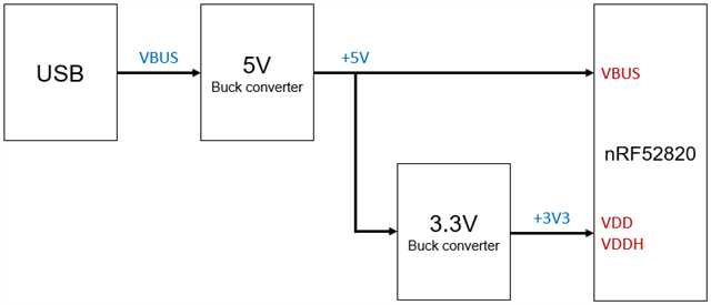
I'm hoping to use the nRF52820 (QFN package) powered by a USB connection (not with external battery).
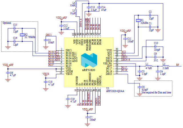
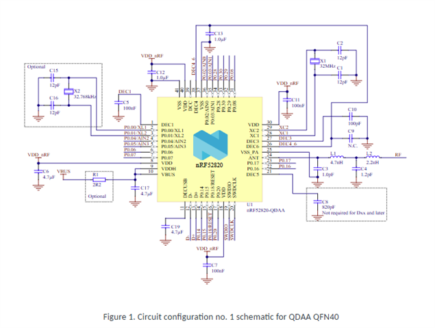
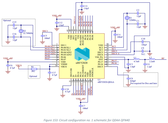
I'm referring to Figure 153 of the datasheet, which shows Circuit Configuration #1 and is the only reference design available showing a USB-powered connection:
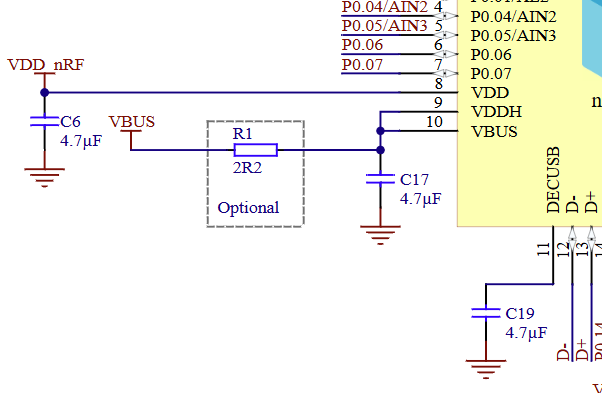
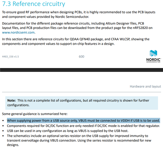
From the notes above in Section 7.3 Reference Circuitry, it seems that when supplying power through USB, VBUS and VDDH must be connected:
My questions are:
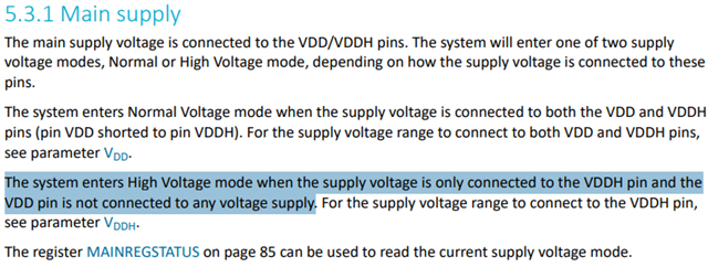
(1) When powering the nRF52820 using USB, it is only possible to use High Voltage mode (Normal Voltage mode is not possible), correct? As shown in Section 5.3.1 Main Supply?
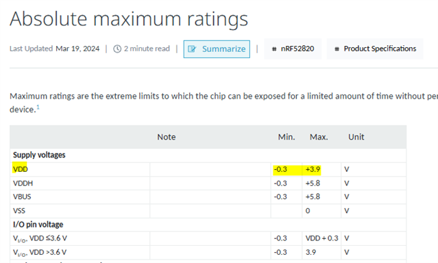
(2) In High Voltage mode, since VDD is internally generated, would this be the voltage rail that SPI and other logic signals pull-up to?
(3) Similarly, when using an external J-Link to flash the nRF52820, the power pin of the J-Link would connect to the internally generated VDD rail?
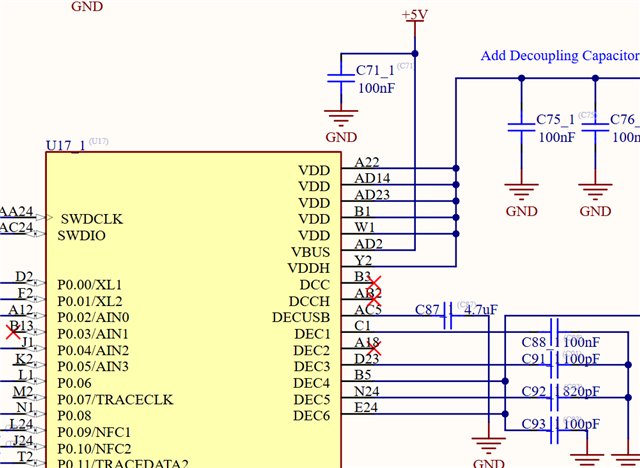
(4) Would a configuration like this be possible where VDD and VDDH are connected and supplied externally, while only VBUS is connected to +5V? If not, why not? FYI, the diagram below uses nRF52840 but the idea would be the same for nRF52820
Thank you!