Issue with charging/battery detection on nPM1300

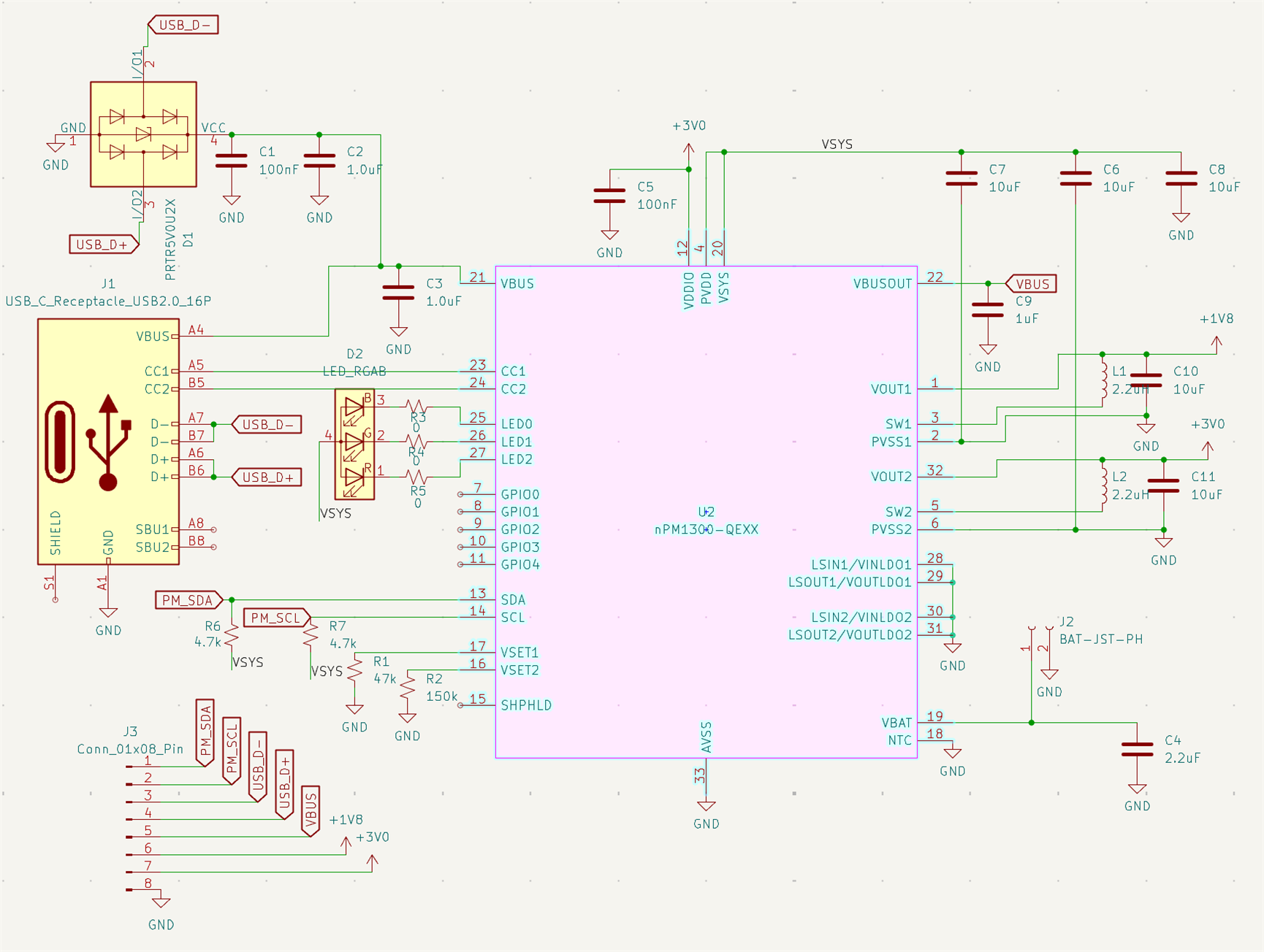
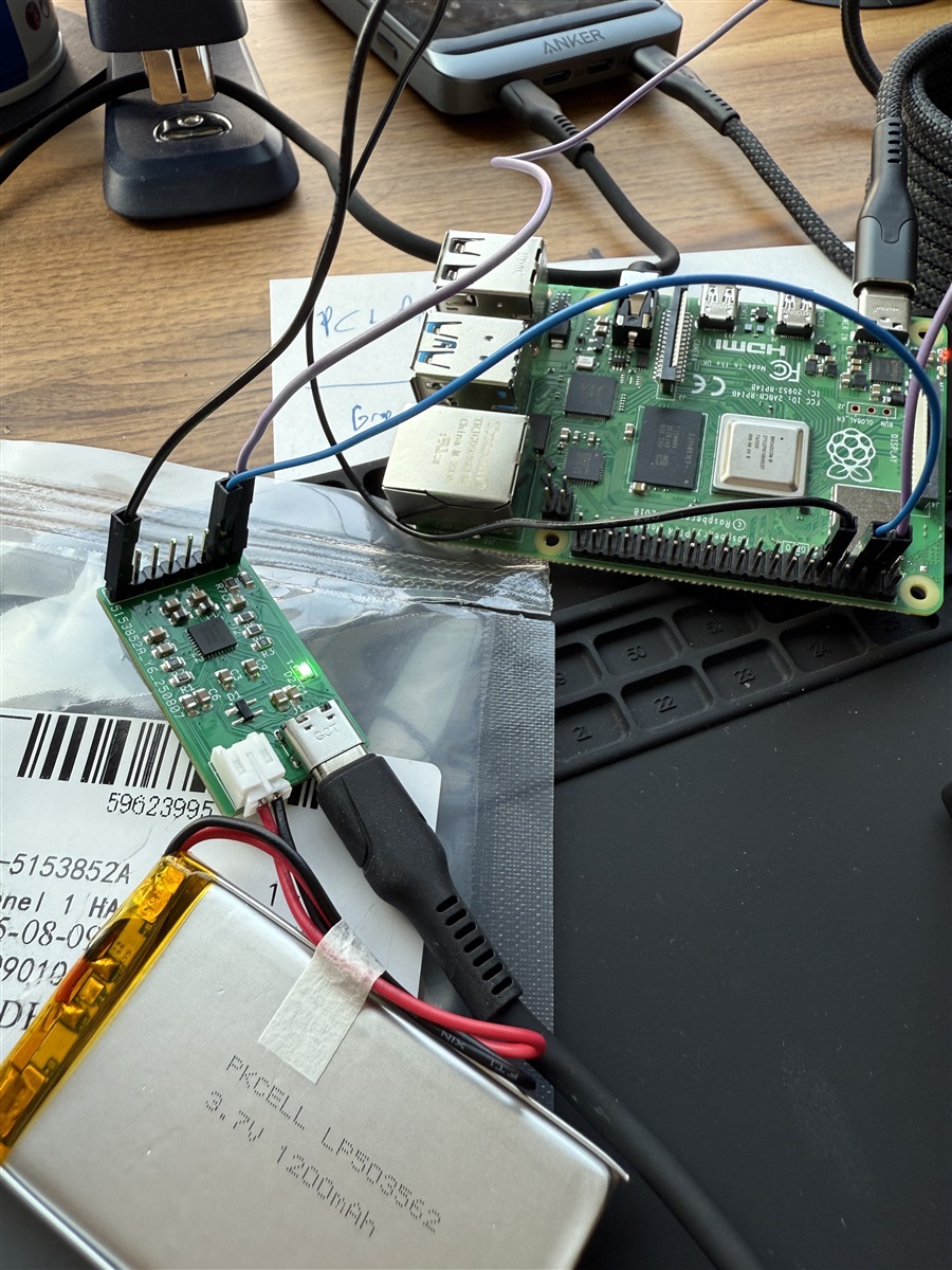
i built a small breakout board for npm1300 (QEAAD0 2516AA) to experiment with it. the twi pins are wired to the i2c ports of a raspberry pi 4 to control it, and i have attached it to a 1200mAh 3.7v lipo battery pack from adafruit (LP503562) with a 2-pin JST connector, along with a usb-c connector. here's the schematic and photo of the board (mostly just taken from the reference design):

it seems like the basics work, i can measure the output of one of the bucks to be roughly at 1.8v and the other roughly at 3v. i can see that the device negotiated the 3a "high power" mode, when plugged into my usb power supply, when polling the USBCDETECTSTATUS register from the raspberry pi:

$ i2cset -y 1 0x6b 0x02 0x05; i2cget -y 10x6b # check USBCDETECTSTATUS
0x0c

if i do this sequence, i can start charging the battery as well:

$ i2cset -y 1 0x6b 0x03 0x06 0x02 i # disable NTC
$ i2cset -y 1 0x6b 0x03 0x0C 0x08 i # set term voltage to 4.2V
$ i2cset -y 1 0x6b 0x03 0x0D 0x08 i # set term voltage to 4.2V
$ i2cset -y 1 0x6b 0x03 0x04 0x01 i # enable charging

at this point, the charge led turns on, and the battery does appear to charge, if i poll the adc to measure battery voltage, i can see that it is increasing. if i poll the battery charging status register, i can also see that the battery is detected and charging:

$ i2cset -y 1 0x6b 0x03 0x34; i2cget -y 1 0x6b # check BCHGCHARGESTATUS
0x09

as i have not set the charge parameters for current, it's charging at the default 34mA very slowly. eventually the battery maybe is charged, but the charge led stays on, though dimmed. if i rapidly poll the BCHGCHARGESTATUS register, i can see that the status is flapping between no battery detected, battery detected, and charging:

$ while [ 1 ]; do i2cset -y 1 0x6b 0x03 0x34; i2cget -y 1 0x6b; done
0x00
0x05
0x00
0x00
0x00
0x00
0x05
0x00
0x05
0x01
0x00


i also notice that if i unplug the battery, the behavior is the same. the charging led stays lit, though dim, and charge status flaps between no battery detected, battery detected, and charging. my two questions:

1. is there something wrong with my circuit or configuration that's causing the ghost battery detection even when the battery is not connected?
2. similarly, is there something i need to be doing differently so that the charger doesn't rapidly flap like that when the battery is connected? ideally the led would turn off when the battery is done charging. 

Parents
  • Hi

    It looks like your issue might be related to the safety timer. The nPM1300 has a tOUTCHARGE = 7 h limit for the CC+CV phases. At 34 mA with a 1200 mAh cell, a full charge would take >40 h, so the safety timer will expire and stop charging. There is also a trickle charging timeout of 10 minutes.

    If you want to keep such a low charge current, you’ll need to periodically clear the safety timer (TASKCLEARSAFETYTIMER),otherwise increase the charge current so the battery finishes within 7 h.

    I’d suggest: Check the charger error registers to confirm if the stop was due to a safety timeout or something else.
    For ex.  when charging stops, check BCHGERRREASON (0x36) — if CHARGETIMEOUT is set, that confirms it. Also check BCHGERRSENSOR (0x37) for context to rule out sensor/threshold faults.

    Do you still see the state flapping when you try with a higher charge current (e.g. >500 mA setting)?

    Even a few µA of leakage through the nPM1300 LED driver or PCB can forward-bias a sensitive LED and make it glow dimly when it’s supposed to be off. Bleed resistor in parallel could help ?

    With no battery, the nPM1300 could still charges and discharges the VBAT input capacitor in a loop, making the status flap and the LED glow faintly.

    Also note that battery detection functionality will no longer be available from D00 version onwards. 
    See the Product Change Notification (PCN) : //docs.nordicsemi.com/bundle/PCN/resource/pcn_213_v1.0.pdf

    Regards 

    Tharaka

Reply
  • Hi

    It looks like your issue might be related to the safety timer. The nPM1300 has a tOUTCHARGE = 7 h limit for the CC+CV phases. At 34 mA with a 1200 mAh cell, a full charge would take >40 h, so the safety timer will expire and stop charging. There is also a trickle charging timeout of 10 minutes.

    If you want to keep such a low charge current, you’ll need to periodically clear the safety timer (TASKCLEARSAFETYTIMER),otherwise increase the charge current so the battery finishes within 7 h.

    I’d suggest: Check the charger error registers to confirm if the stop was due to a safety timeout or something else.
    For ex.  when charging stops, check BCHGERRREASON (0x36) — if CHARGETIMEOUT is set, that confirms it. Also check BCHGERRSENSOR (0x37) for context to rule out sensor/threshold faults.

    Do you still see the state flapping when you try with a higher charge current (e.g. >500 mA setting)?

    Even a few µA of leakage through the nPM1300 LED driver or PCB can forward-bias a sensitive LED and make it glow dimly when it’s supposed to be off. Bleed resistor in parallel could help ?

    With no battery, the nPM1300 could still charges and discharges the VBAT input capacitor in a loop, making the status flap and the LED glow faintly.

    Also note that battery detection functionality will no longer be available from D00 version onwards. 
    See the Product Change Notification (PCN) : //docs.nordicsemi.com/bundle/PCN/resource/pcn_213_v1.0.pdf

    Regards 

    Tharaka

Children
  • hey tharaka-- really appreciate your advice here. i checked the two charger status registered you suggested. they are both zero while the light is dim and the charge status is flapping (battery unplugged or plugged in is the same):

    $ i2cset -y 1 0x6b 0x03 0x36; i2cget -y 1 0x6b
    0x00
    $ i2cset -y 1 0x6b 0x03 0x37; i2cget -y 1 0x6b
    0x00

    i also am frequently resetting the device to try new parameters and take more measurements, so i don't think i've ever continuously had the charger running for 7 hours anyway.

    for your next suggestion, i tried raising the charge current before starting the charger. here are the commands i'm using now:

    i2cset -y 1 0x6b 0x00 0x01 0x01 i  # reset
    $ i2cset -y 1 0x6b 0x03 0x06 0x02 i  # disable ntc
    $ i2cset -y 1 0x6b 0x02 0x01; i2cget -y 1 0x6b  # check initial vbus limit
    0x01
    $ # ^ it's 100mA
    $ i2cset -y 1 0x6b 0x02 0x01 0x08 i  # set vbus limits to 800mA 
    $ i2cset -y 1 0x6b 0x02 0x02 0x08 i  # set vbus limits to 800mA
    $ i2cset -y 1 0x6b 0x02 0x00 0x01 i  # commit vbus limits
    i2cset -y 1 0x6b 0x03 0x08 0x7d i  # set charge current to 500mA
    i2cset -y 1 0x6b 0x03 0x0a 0xcf i  # set discharge current to 1A
    $ i2cset -y 1 0x6b 0x03 0x0b 0x01 i  # set discharge current to 1A
    i2cset -y 1 0x6b 0x03 0x0C 0x08 i # set term voltage to 4.2V
    $ i2cset -y 1 0x6b 0x03 0x0D 0x08 i # set term voltage to 4.2V
    $ i2cset -y 1 0x6b 0x03 0x04 0x01 i # enable charging

    at this point i don't really see a change in behavior. the device continues to flap charging status and the led stays dimly lit. 

    i'm less concerned about the case where the battery is disconnected, but just to test, i also removed the 10uF cap on the VBAT line and it did not appear to change the behavior in either case of the battery being connected or disconnected.


    after messing with everything a bit more, i did discover one potential issue (though i'm still not sure of the cause). even though i am setting the battery term voltage to 4.2, i find that if i measure the voltage on the battery terminals during this charge flapping (or even with the battery unplugged), i get 4.8v. curiously, i if i lower the term voltage setting to 3.5v, i see that it now measures around 4.3v and after a few seconds of charging, the led turns off (no error status is set). the charge status says that the battery charge is completed (this might even be correct, as i can measure 4.2v across the battery when unplugged):

    $ i2cset -y 1 0x6b 0x03 0x34; i2cget -y 1 0x6b
    0x03

    at this point the charge led is fully turned off, so it seems if the charger is operating as intended, and there does not appear to be a leakage current issue with the LED.

    upon re-measuring the breakout pins, i notice that the measurements seem off:
    - VBUSOUT 4.98V (probably ok)
    - VOUT1 1.94 (should be 1.8v)
    - VOUT2 3.29 (should be 3.0v)

    i guess +/- 10% isn't crazy but given how far off the charge voltage seems to be, i wonder if there's something wrong with my pcb design that would create these kind of issues?

  • Hi 

    Thanks for the update. It sounds like the issue is not coming from the PMIC or the battery pack.

    I asked our HW design experts to review the PCB design, it looks like your PCB design could potentially be a major contributor to the issues you highlighted.

    Yes, the 4.8 V you are seeing on the battery terminal is definitely concerning. VOUT2 also doesn’t look correct from your measurements.

    The high-current traces are very narrow and spread across the board in a way that can cause large voltage drops and noise. In addition, there doesn’t seem to be a solid GND plane. Without a low-impedance GND reference, it’s hard to predict how current flows, and this can easily lead to level shifting/bouncing that makes comparator thresholds behave unpredictably.

    For a 2-layer board, it is critical to dedicate one layer as a solid GND plane. In your current layout this is essentially missing. If possible, I would also recommend moving to at least a 4-layer board, which will allow you to have a solid GND plane and make the routing much cleaner.

    As a reference, please take a look at:

    We strongly suggest reworking the PCB layout based on these resources.

    Once you have reworked the layout based on the guidelines, feel free to share it here before moving forward with manufacturing. We’ll be happy to review it again.

    Regards 

    Tharaka

Related