Hi all,
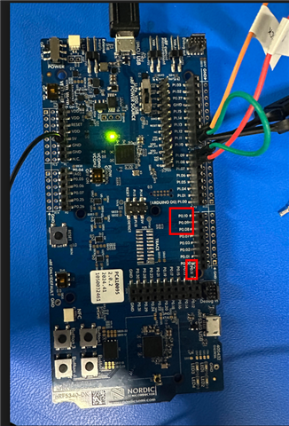
I'm trying to enable the SPIM4 peripheral on the dedicated high-speed pins (P0.08 SCK, P0.09 MISO, P0.10 MOSI, P0.11 CS) on the nRF5340DK, but I'm seeing no activity at all on my logic analyzer.
Background:
My goal is to connect an external ADC. Previously, I had the ADC working with SPIM4 on a different set of pins (P1.12 - P1.15 default configuration for the bus) using Zephyr's adc_dt sample as a base. Although I got it working, my application requires a better resolution, so I switched to the dedicated P0.08-P0.11 pins. When that didn't work, I simplified the problem to a basic SPI loopback test (physically connecting P0.09 to P0.10) to isolate the issue, but the problem remains. I am pretty confident, that it is not my board overlay file, as it pretty much matches the overlays described in the following discussion post: SPI4 with multiple CS as well as verified in this documentation page: https://docs.nordicsemi.com/bundle/ps_nrf5340/page/chapters/pin.html
Current Behavior (Loopback Test):
1. The application builds and runs fine (both secure and non-secure).
2. The printk log shows the SPI device is ready (spi@a000) and the spi_transceive() function is being called in a loop.
3. The SPI driver logs show the transaction completes with status 0 (success). The RX buffer is all zeros, as expected if the loopback isn't working.
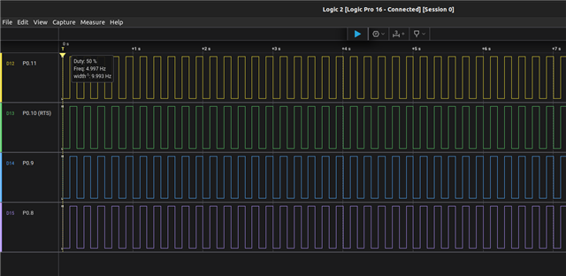
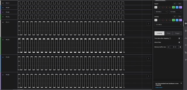
4. Despite all this there is no signal activity showing up on my logic analyzer for SCK, MISO, MOSI, or CS. Which is interesting given that I expect at least the SCK to show up on my logic analyzer.
Checks Performed:
- Verified the final build/zephyr/zephyr.dts shows spi@a000 with the correct pinctrl-0 and cs-gpios applied.
- Confirmed there are no obvious pin conflicts with enabled peripherals in the DTS.
- Tested both secure (.../cpuapp) and non-secure (.../cpuapp_ns) builds, with a corresponding _ns.overlay file for the latter.
- Verified physical connections (loopback jumper and via connectivity test).
My Question:
Why would the nrfx SPIM driver report a successful transaction if the pins are not being driven? Is there a known issue or a required Kconfig option for enabling the high-speed SPI pins that I might be missing? Any known conflicts with the default board DTS that need to be explicitly disabled?
I have attached my application code, logs, prj.conf and board overlay file below. Any help or guidance would be much appreciated. Thank you!
main.c:
#include <zephyr/kernel.h>
#include <zephyr/device.h>
#include <zephyr/devicetree.h>
#include <zephyr/drivers/spi.h>
#include <zephyr/sys/printk.h>
#include <inttypes.h>
#include <stddef.h>
#include <stdint.h>


#define SPI_DEV DT_ALIAS(spi_loopback)
static const struct device *spi_dev = DEVICE_DT_GET(SPI_DEV);

static const struct spi_config spi_cfg = {
	.operation = SPI_WORD_SET(8) | SPI_TRANSFER_MSB,
	.frequency = 4000000,
	.slave = 0,
};

int main(void)
{
	if (!device_is_ready(spi_dev)) {
		printk("SPI device not ready\n");
		return 0;
	}

	printk("SPI Loopback Test Started on %s\n", spi_dev->name);

	uint8_t tx_buffer[] = {0xDE, 0xAD, 0xBE, 0xEF, 0xFE, 0xED, 0xBA, 0xBE};
	uint8_t rx_buffer[sizeof(tx_buffer)];

	struct spi_buf tx_buf_set = { .buf = tx_buffer, .len = sizeof(tx_buffer) };
	struct spi_buf rx_buf_set = { .buf = rx_buffer, .len = sizeof(rx_buffer) };

	struct spi_buf_set tx = { .buffers = &tx_buf_set, .count = 1 };
	struct spi_buf_set rx = { .buffers = &rx_buf_set, .count = 1 };

	while (1) {
		int error = spi_transceive(spi_dev, &spi_cfg, &tx, &rx);

		if (error) {
			printk("SPI transceive error: %d\n", error);
		} else {
			printk("TX -> ");
			for (size_t i = 0; i < sizeof(tx_buffer); i++) {
				printk("%02X ", tx_buffer[i]);
			}
			printk("\n");

			printk("RX <- ");
			for (size_t i = 0; i < sizeof(rx_buffer); i++) {
				printk("%02X ", rx_buffer[i]);
			}
			printk("\n");

			if (memcmp(tx_buffer, rx_buffer, sizeof(tx_buffer)) == 0) {
				printk("Result: SUCCESS\n\n");
			} else {
				printk("Result: FAILED - Check MISO/MOSI connection\n\n");
			}
		}

		tx_buffer[0]++;

		k_sleep(K_SECONDS(1));
	}
	return 0;
}
prj.conf:
# SPI Configuration
CONFIG_SPI=y
CONFIG_SPI_NRFX=y

# GPIO Configuration
CONFIG_GPIO=y

# Logging and Console Output
CONFIG_PRINTK=y
CONFIG_SERIAL=y
CONFIG_UART_CONSOLE=y

CONFIG_LOG=y
CONFIG_LOG_MODE_IMMEDIATE=y

CONFIG_SPI_LOG_LEVEL_DBG=y
nrf5340df_nrf5340_cpuapp.overlay:
/ {
	aliases {
		spi-loopback = &spi4;
	};
};
&pinctrl {
    spi4_default: spi4_default {
        group1 {
            psels = <NRF_PSEL(SPIM_SCK, 0, 8)>,
                    <NRF_PSEL(SPIM_MOSI, 0, 10)>,
                    <NRF_PSEL(SPIM_MISO, 0, 9)>;

        };
    };

    spi4_sleep: spi4_sleep {
         group1 {
            psels = <NRF_PSEL(SPIM_SCK, 0, 8)>,
                    <NRF_PSEL(SPIM_MOSI, 0, 10)>,
                    <NRF_PSEL(SPIM_MISO, 0, 9)>;
            low-power-enable;
        };
    };
};

&spi4 {
	compatible = "nordic,nrf-spim";
	status = "okay";
	pinctrl-0 = <&spi4_default>;
	pinctrl-1 = <&spi4_sleep>;
	pinctrl-names = "default", "sleep";
	cs-gpios = <&gpio0 11 GPIO_ACTIVE_LOW>;

};

&arduino_adc{
    status="disabled";
};
&led0 {
    status = "disabled";
};

&led1 {
    status = "disabled";
};

&led2 {
    status = "disabled";
};

&led3 {
    status = "disabled";
};
&qspi{
    status = "disabled";
};
Example Application Log:
*** Booting Zephyr OS build v4.2.0-1493-gadd9e60c1d80 ***
SPI Loopback Test Started on spi@9000
[00:00:00.259,552] <dbg> spi_nrfx_spim: spi_context_buffers_setup: tx_bufs 0x20001270 - rx_bufs 0x20001278 - 1
[00:00:00.269,989] <dbg> spi_nrfx_spim: spi_context_buffers_setup: current_tx 0x20001260 (1), current_rx 0x20001268 (1), tx buf/len 0x20001250/8, rx buf/len 0x20001258/8
[00:00:00.285,583] <dbg> spi_nrfx_spim: spi_context_update_tx: tx buf/len 0/0
[00:00:00.293,090] <dbg> spi_nrfx_spim: spi_context_update_rx: rx buf/len 0/0
[00:00:00.300,628] <dbg> spi_nrfx_spim: finish_transaction: Transaction finished with status 0
TX -> DE AD BE EF FE ED BA BE
RX <- 00 00 00 00 00 00 00 00
Result: FAILED - Check MISO/MOSI connection