
Hi
I am trying to use the two GPIO pins. One GPIO pin is configured as a input and connected externally to a button.
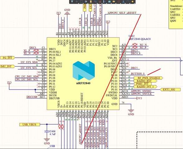
The second is configured as an output pin. I want to press the button and trigger the second GPIO pin to output a low signal
The button press will trigger a hardware nRESET. see attached schematics
I use the PPI to connect them, not sure if this is the way to do it. Especially the TEP and EEP register values not sure about
//Button pins interface init
    NRF_P1->PIN_CNF[6] = 0x0003000C;     //Nrf52 button GPIO input pin port P1.06, internal pull up
    NRF_GPIOTE->INTENCLR = 0x00000001;   //Disable interupts on CONFIG[0] pin
    NRF_GPIOTE->CONFIG[0] = 0x00022601;  //Set BUTTON press on port P1.06 as a GPIOTE EVENT to generate an interrupt event when going from HIGH to LOW.
    NRF_GPIOTE->EVENTS_IN[0] = 0;        // Clear any potential events that could have occured during configuration
    NRF_GPIOTE->INTENSET = 0x00000001;   //Enable interupts on CONFIG[0] pin

    //nRF52 APPCPU_SELF_nRESET
    NRF_P1->OUTSET = 0x00000400;        //Set APPCPU_SELF_nRESET GPIO output pin HIGH.
    NRF_P1->PIN_CNF[10] = 0x0000000F;   //Nrf52 APPCPU_SELF_nRESET GPIO output pin port P1.10, internal pull up
    NRF_GPIOTE->INTENCLR = 0x00000002;  //Disable interupts on CONFIG[1] pin
    NRF_GPIOTE->CONFIG[1] = 0x00122A03; //Set GPIO output port P1.10 as a GPIOTE TASK (HIGH_to_LOW) to trigger on a event.
    NRF_GPIOTE->EVENTS_IN[1] = 0;       // Clear any potential events that could have occured during configuration
    NRF_GPIOTE->INTENSET = 0x00000002;  //Enable interupts on CONFIG[1] pin

    //PPI channel configuration 0 config. Makes nRF52 self reset trigger on button press
    NRF_PPI->CHENCLR = 0x00000001;
    NRF_PPI->CH[0].EEP = 0x40006100;
    NRF_PPI->CH[0].TEP = 0x40006104;
    NRF_PPI->CHENSET = 0x00000001;
kr
Øystein

