nPM2100 : stabilisation of the current consumption when the output power is low

Hello,

I have a question about the power consumption stabilisation of the nPM2100.

We configured the nPM2100 with the pins directly to obtain a V_OUT of 3V with a 2477 battery. We varied the voltage from 3.2V to 1V and everything worked fine.

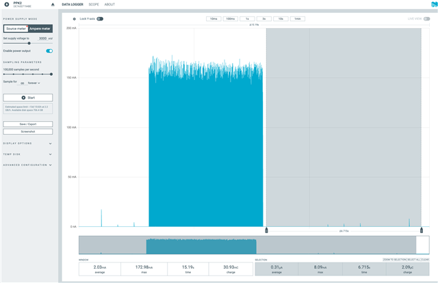
When we switch our device to OFF mode, the consumption is ~5uA (V_BAT = 3V). This is a good result, except that it takes ~3 minutes to achieve this result (I will send the PPK2 measure). We would therefore need to achieve this result in 10 seconds in order to validate the power consumption of this product for the production process.

When the battery is new, the output voltage can be bigger than 3.2V. I think using the auto mode is the better option (HP/LP/ULP/PT).

Initially, we do not have access to the i2c pins to configure the device differently. Could this have been corrected using the BOOST.GPIO, BOOST.PIN or BOOST.OPER registers?

We also have a V_INT capacity of 10uF (the same installed in the evaluation kit). I have read that a value of 10 uF to 22 uF is recommended for a lithium battery.

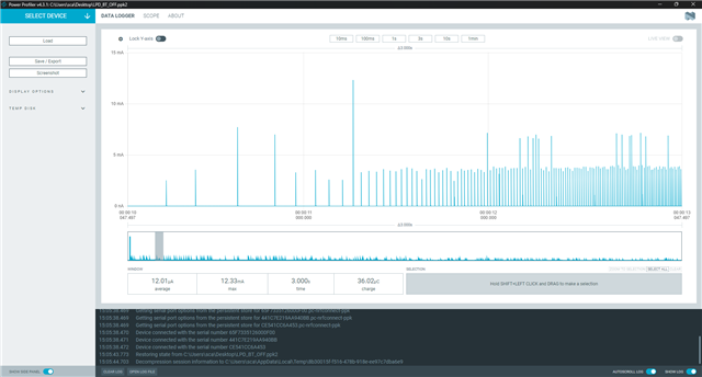
OFF START (After 0 sec / 12.01uA) OK

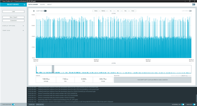
OFF MIDDLE (After 10 sec / 108.93uA) NOT OK

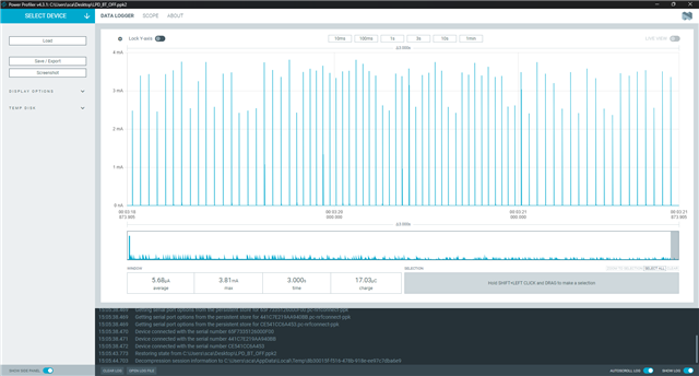
OFF END (3 minutes / 5.68uA) OK


How can these good results be achieved in a shorter time?

What are the steps involved?

Thank you for your help.

Parents
  • Hi  ,

    For this use case, "auto mode" is recomended. This will cause the BOOST regulator to automatically use pass-through mode when VBAT > VOUT. No need to change BOOST.GPIO, BOOST.PIN or BOOST.OPER registers in this case.

    These PPK2 measurements are taken from the VBAT side? That is, PPK2 is acting as a power supply for VBAT? What does the VOUT load profile look like at this time?

    Would it also be possible to look at the schematics for the nPM2100 to see if there could be potential issues? That can be done via a private techsupport case.

    The "discharge"-type behavior makes me wonder if there could be capacitance somewhere that affects performance.

    I tried to recreate the behavior on an nPM2100 EK, but I have been unsuccessful so far. This is the profile I see when connecting and disconnecting a 10 mA constant current load, using 100 uF VINT capacitance:

    Note that the PPK2 struggles a bit when measuring the nPM2100 (and other BOOST converters presumably), due to the very short current spikes seen on the VBAT side. The 100 kHz sampling rate of the PPK2 does not capture all of these, and it is easy to get an underestimated current measurement value.

    Best regards,

    Audun

  • Dear Audun,

    Thank you for your answer.

    Ok great. Auto mode selection is nice when having V_BAT > V_OUT.
    No need to use the registers (for the moment).

    Yes, the measurments are made from the V_BAT side of the instruments.
    The PPK2 is used to provide the V_BAT voltage to our instruments (in this case it was 3V)(and also to check the currents).
    The load profile is a constant charge which is around 6 uA with a V_OUT of 3V (the instrument is in the OFF mode).

    Ok I can send the schematics of the NPM2100 in a techsupport case.

    The capacitor is not 100 uF but 10 uF instead (which is a recommanded value given by your team).
    I just confirmed that with the schematics.

    We know this point about the PPK2. Sometime the PPK2 gives a wrong current with those high frequencies.
    We use an amperemeter (in uA range) to check the values given by the PPK2.
    With this option, the current of the PPK2 are quite the same as the one given by the amperemeter.

    I look forward hearing from you soon.

    Best regards,

  • No problem, SCF,

    I am sadly not able to recreate the issue on an nPM2100-EK using 10 uF VINT either.. 

    I think next step would be a design review via private techsupport to look for potential culprits. 

    As a side note, have you tried already or are you able to connect your load to an nPM2100 EK to verify if you see the same behavior there?

    Best regards,

    Audun

  • Hello Audun,

    I checked with the EK:

    1) PPK2 is giving the voltage to the EK.
    2) The EK is supplying the instrument.
    3) The instrument is placed in the OFF mode.
    4) The current suppying the instrument (EK V_OUT) go to 1uA and rises directly to more than 200uA and after 3 minutes it stabilises to around 10 uA.

    I let you check with the schematics if you see something wrong.

    I can also tell you that when I put the nPM2100 in the ship mode, the current goes directy to 65nA with no delay.

    Thank you Nordic

  • Hello, 

    Have you tried powering the instrument without nPM2100 if you get the same behavior? Anyway it sounds like something is consuming current at the instrument side and nPM2100 is just supplying it. It can be for example I2C lines/pull-ups. 

  • Dear Nordic team,

    You were wright: I need to place some pull down resistors when the device is turned OFF at the output of our sensor.

    Now, when I turn all the system OFF the current consumption is around 3µA under a VBAT of 3V. This is a good result.

    Be carefull to not check those little currents only with the PPK2. I need to use an ammeter (µA range) with the PPK2 to obtain correct values. I also use the terminal to not discard any samples.

    Thank you Nordic for your help!

Reply
  • Dear Nordic team,

    You were wright: I need to place some pull down resistors when the device is turned OFF at the output of our sensor.

    Now, when I turn all the system OFF the current consumption is around 3µA under a VBAT of 3V. This is a good result.

    Be carefull to not check those little currents only with the PPK2. I need to use an ammeter (µA range) with the PPK2 to obtain correct values. I also use the terminal to not discard any samples.

    Thank you Nordic for your help!

Children
No Data
Related