AIN0 and AIN1 always returning the maximum value on nRF54L15 DK

I am struggling with the ADC API on the nRF54L15 dev kit. I am using NCS 3.1.0

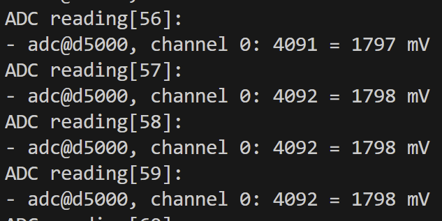
I started with the "samples/drivers/adc/adc_dt" sample as a starting point. Using AIN4 (Channel 0) worked, giving me readings from 900mV to 1800mV (using the Nordic PPKII).

Using exactly the same code, I started chaning the overlay.

The first problem I encountered was using AIN0 caused the logging to stop as soon as I applied power (!).

With AIN0 apparently useless, I switched to AIN1 (P1.05). My overlay is here

/ {
	zephyr,user {
		io-channels = <&adc 0>;
	};
};

&adc {
	#address-cells = <1>;
	#size-cells = <0>;

	channel@0 {
		reg = <0>;
		zephyr,gain = "ADC_GAIN_1_2";
		zephyr,reference = "ADC_REF_INTERNAL";
		zephyr,acquisition-time = <ADC_ACQ_TIME_DEFAULT>;
		zephyr,input-positive = <NRF_SAADC_AIN1>;
		zephyr,resolution = <12>;
		zephyr,oversampling = <8>;
	};
};

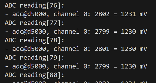
Here is the output I get. 

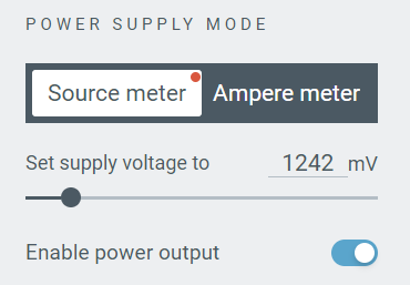
I am only applying 1200mV to PIN

If I switch from AIN0 to AIN4, the reading is correct.

Are AIN0 and AIN1 special in any way?

Whilst searching the forum, I came across this:  nRF54L15 UART20 on non-standard pins results in garbage data 

Is this my problem with the DK? If so, would this be an issue if I was using a module?

Parents
  • Hello,

    ''The first problem I encountered was using AIN0 caused the logging to stop as soon as I applied power (!).''

    The operational voltage of nRF4l15 is 1.8 to 3.6V. I can see on the PPK2, you set 1.24V.

    If the supply voltage is set to 1242 mV (1.242 V), this is below the minimum required operating voltage for the device. Operating the nRF54L15 below 1.7 V is not supported and can lead to unpredictable behavior, including issues with peripherals like the ADC.

    Also, On the nRF54L15 DK, AIN4 is used instead of the AIN0 as AIN0 (P1.04) pin is used by default for UART. If you want to use ADC without conflicts, you can pick another channel like AIN4 (as you did), which maps to a different pin not already reserved for UART.

    Thanks.

    BR
    Kazi

  • Apologies for the misunderstanding!

    The board is being powered via USB and is fully operational (It's running a Matter application)

    I realise that I'm using a different ground reference with the PPK2, which might be causing me some problems.

    I have two follow up questions:

    I understand the issue with AIN0 on the DK. Whilst waiting for an answer, I started using AIN5 and AIN6. AIN5 works as expected. AIN6 does not. It gives me a very inaccurate reading. Does time PIN have special consideration on the DK?

    If I use an nRF54L15 module, can I use AIN0 and AIN1?

  • Tom McGuinness said:
    AIN6 does not. It gives me a very inaccurate reading.

    This pin is connected to the button on the DK, this is likely why you get a strange value. 


    Tom McGuinness said:
    If I use an nRF54L15 module, can I use AIN0 and AIN1?

    If the module does not have any buttons or other sensors connected to the pins there should be no issues using these pins. 


    https://docs.nordicsemi.com/bundle/ug_nrf54l15_dk/page/UG/nRF54L15_DK/hw_desription/hw_description.html 
    You can check the schematic for the DK to se what pins are connected to what things as well. 

    Regards,
    Jonathan

Reply Children
No Data
Related