This post is older than 2 years and might not be relevant anymore
More Info: Consider searching for newer posts

How to enable Jlink for custom board for nRF52832 DK

I am using nRF52832 DK. I have connected our custom board using Debug out and loading code is successful for custom board. I loaded radio_test code. Now I want to test the radio parameters. For that any settings required on the DK board to enable Jlink for custom board?????? In my system Jlink isi detected in com ports, but I am not getting Radio test in terminal. Please provide any settings required to enable Jlink for custom board.

Thanks in Advance.

Parents
  • FormerMember
    0 FormerMember

    The problem may be that the UART pins on the external board are not connected to anything. The debugger pins does only consist of SWDCLK, SWDIO, GND and VDD.

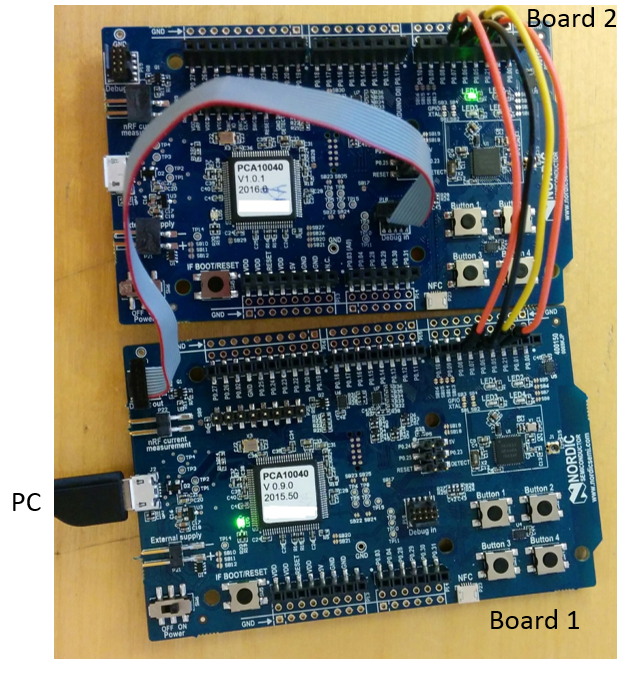
    Update 15.0316: The image below shows use the nRF52 DK (board 1) to

    1. program a PCB that is not connected to a debugger (board 2)
    2. print UART data from board 2 on the PC connected to board 1. The UART cables are connected to the defined UART pins on Board 1 and Board 2, respectively.

    image description

  • FormerMember
    0 FormerMember in reply to FormerMember

    No, there is no solder bridges that has to be changed. When the external PCB is powered, the nRF52-DK will use P19 (Debug out) for programming instead of programming the chip on the DK. You can read more in the nRF52-DK user guide.

Reply Children
No Data
Related