Hi, I am working on a project where ECG data can be send wirelessly. For that I am using ADS1298 and nRF52833. I am very new to it. I have connected the nRF52833 SPI lines with the ADS1298. For power, since the DRDY was not falling when I used the power from nRF52833, I am using the MMB0 board by the ADS1298 ECG FE itself. Still I am not getting any output. I am not sure what I am not getting right. I can see the DRDY going low and coming back, the CS and SCLK are all working but there is no output from DOUT(MISO). What could be reasons? I saw some old queries about the issue and they are mentioning about the timing of CS. How to check that? I have also provided the code that I am using.
#include <stdint.h>
#include <stdbool.h>
#include "nrf_drv_spi.h"
#include "nrf_drv_gpiote.h"
#include "nrf_gpio.h"
#include "nrf_delay.h"
#include "app_error.h"
#include "nrf_log.h"
#include "nrf_log_ctrl.h"
#include "nrf_log_default_backends.h"
#define PIN_SPI_SCK 36
#define PIN_SPI_MOSI 34
#define PIN_SPI_MISO 33
#define PIN_SPI_CS 35
#define PIN_DRDY 37
#define PIN_START 38
#define PIN_RESET 39
// -------------------- SPI and ADS constants --------------------
static const nrf_drv_spi_t spi = NRF_DRV_SPI_INSTANCE(0);
#define ADS_FRAME_BYTES 27 // 3 status + 8 * 3 bytes
// ADS1298 commands
#define CMD_WAKEUP 0x02
#define CMD_STANDBY 0x04
#define CMD_RESET 0x06
#define CMD_START 0x08
#define CMD_STOP 0x0A
#define CMD_RDATAC 0x10
#define CMD_SDATAC 0x11
#define CMD_RDATA 0x12
// -------------------- globals --------------------
static volatile bool drdy_flag = false;
// -------------------- low-level helpers --------------------
// Manual CS control (we will initialize SPI with ss_pin = NOT_USED)
static inline void cs_low(void) { nrf_gpio_pin_clear(PIN_SPI_CS); }
static inline void cs_high(void) { nrf_gpio_pin_set(PIN_SPI_CS); }
// send a single-command (CS low, send byte, CS high)
static void ads_cmd(uint8_t cmd)
{
cs_low();
ret_code_t rc = nrf_drv_spi_transfer(&spi, &cmd, 1, NULL, 0);
APP_ERROR_CHECK(rc);
cs_high();
nrf_delay_us(2);
}
// write single register (WREG reg, count=0)
static void ads_write_reg(uint8_t reg, uint8_t val)
{
uint8_t buf[3];
buf[0] = 0x40 | (reg & 0x1F); // WREG
buf[1] = 0x00; // write 1 register (N-1)
buf[2] = val;
cs_low();
APP_ERROR_CHECK(nrf_drv_spi_transfer(&spi, buf, 3, NULL, 0));
cs_high();
nrf_delay_us(2);
}
// read single register (RREG reg, count=0)
static uint8_t ads_read_reg(uint8_t reg)
{
uint8_t hdr[2];
uint8_t val = 0;
hdr[0] = 0x20 | (reg & 0x1F); // RREG
hdr[1] = 0x00; // read 1
cs_low();
APP_ERROR_CHECK(nrf_drv_spi_transfer(&spi, hdr, 2, NULL, 0));
nrf_delay_us(2);
APP_ERROR_CHECK(nrf_drv_spi_transfer(&spi, NULL, 0, &val, 1));
cs_high();
return val;
}
// -------------------- DRDY handler --------------------
static void drdy_handler(nrf_drv_gpiote_pin_t pin, nrf_gpiote_polarity_t action)
{
(void)pin; (void)action;
drdy_flag = true; // signal main loop to read frame
}
static void drdy_init(void)
{
if (!nrf_drv_gpiote_is_init()) APP_ERROR_CHECK(nrf_drv_gpiote_init());
nrf_drv_gpiote_in_config_t in_cfg = GPIOTE_CONFIG_IN_SENSE_HITOLO(true); // falling edge
in_cfg.pull = NRF_GPIO_PIN_PULLUP;
APP_ERROR_CHECK(nrf_drv_gpiote_in_init(PIN_DRDY, &in_cfg, drdy_handler));
nrf_drv_gpiote_in_event_enable(PIN_DRDY, true);
}
// -------------------- ADS1298 init sequence --------------------
static void ads1298_init_sequence(bool test_mode)
{
// Ensure chip not in RDATAC (stop continuous read so registers writable)
ads_cmd(CMD_SDATAC);
nrf_delay_ms(2);
// Disable lead-off detection (LOFF)
ads_write_reg(0x04, 0x00); // LOFF
ads_write_reg(0x0F, 0x00); // LOFF_SENSP
ads_write_reg(0x10, 0x00); // LOFF_SENSN
ads_write_reg(0x11, 0x00); // LOFF_FLIP
// Optionally LOFF_STATP/LOFF_STATN etc left default
// CONFIG registers
// CONFIG1: set 500 SPS, HR mode if you want
// Use 0x86 was used earlier by you (HR mode, 500SPS). If needed use 0x02 (regular mode, 500SPS).
ads_write_reg(0x01, 0x86); // CONFIG1 = 0x86 (HR, 500 SPS)
if (test_mode) {
// CONFIG2: enable internal test signal
// 0xD3 is a common value used earlier: bits to enable test and internal signal type
ads_write_reg(0x02, 0xD3);
} else {
ads_write_reg(0x02, 0x10); // CONFIG2 normal
}
ads_write_reg(0x03, 0xDC); // CONFIG3 typical (ref buffer on etc)
// Enable channels: CH1..CH8
// 0x00 = normal electrode input enabled
// If test_mode, route CH1 to test input (0x05)
for (uint8_t ch = 0; ch < 8; ++ch) {
uint8_t addr = 0x05 + ch;
if (test_mode && ch == 0) {
ads_write_reg(addr, 0x05); // CH1 test signal
} else {
ads_write_reg(addr, 0x00); // normal electrode input, not power-down
}
}
// Done: restart continuous read and start conversions
ads_cmd(CMD_RDATAC);
nrf_delay_ms(1);
ads_cmd(CMD_START);
nrf_delay_ms(1);
}
// -------------------- Frame read helper --------------------
static inline int32_t s24_to_s32(const uint8_t *b)
{
int32_t v = ((int32_t)b[0] << 16) | ((int32_t)b[1] << 8) | ((int32_t)b[2]);
if (v & 0x00800000) v |= 0xFF000000; // sign extend
return v;
}
// -------------------- Main --------------------
int main(void)
{
// Init logging
APP_ERROR_CHECK(NRF_LOG_INIT(NULL));
NRF_LOG_DEFAULT_BACKENDS_INIT();
NRF_LOG_INFO("ADS1298 nRF52833 example starting...");
NRF_LOG_FLUSH();
// Configure control GPIOs
nrf_gpio_cfg_output(PIN_SPI_CS);
nrf_gpio_cfg_output(PIN_START);
nrf_gpio_cfg_output(PIN_RESET);
#ifdef PIN_PWDN
nrf_gpio_cfg_output(PIN_PWDN);
nrf_gpio_pin_set(PIN_PWDN); // enable device
#endif
// Idle states
nrf_gpio_pin_set(PIN_SPI_CS); // CS high (inactive)
nrf_gpio_pin_set(PIN_START); // START high (enable conversions)
nrf_gpio_pin_set(PIN_RESET); // keep reset high initially
// Reset pulse
nrf_gpio_pin_clear(PIN_RESET);
nrf_delay_ms(5);
nrf_gpio_pin_set(PIN_RESET);
nrf_delay_ms(20);
// Init SPI (manual CS)
nrf_drv_spi_config_t spi_cfg = NRF_DRV_SPI_DEFAULT_CONFIG;
spi_cfg.ss_pin = NRF_DRV_SPI_PIN_NOT_USED;
spi_cfg.sck_pin = PIN_SPI_SCK;
spi_cfg.mosi_pin = PIN_SPI_MOSI;
spi_cfg.miso_pin = PIN_SPI_MISO;
spi_cfg.frequency = NRF_DRV_SPI_FREQ_1M; // you can lower to 125k for debugging
spi_cfg.mode = NRF_DRV_SPI_MODE_1;
spi_cfg.bit_order = NRF_DRV_SPI_BIT_ORDER_MSB_FIRST;
APP_ERROR_CHECK(nrf_drv_spi_init(&spi, &spi_cfg, NULL, NULL));
// Setup DRDY interrupt
drdy_init();
// Quick ID check: stop RDATAC and read ID register
ads_cmd(CMD_SDATAC);
nrf_delay_ms(2);
uint8_t id = ads_read_reg(0x00);
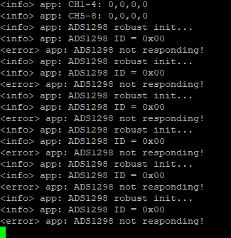
NRF_LOG_INFO("ADS1298 ID = 0x%02X", id);
NRF_LOG_FLUSH();
// Choose mode here: true = internal test signal; false = ECG electrode mode
bool test_mode = true; // <-- change as needed
if ((id & 0xF0) == 0x90 || id != 0x00) {
NRF_LOG_INFO("ADS seems present, configuring...");
ads_init_sequence(test_mode);
} else {
NRF_LOG_ERROR("ADS not responding. Check power, PWDN, CLKSEL, reset, wiring.");
}
// Buffers for frame read
uint8_t tx[ADS_FRAME_BYTES];
uint8_t rx[ADS_FRAME_BYTES];
// main loop: wait for drdy_flag and read a frame
while (1) {
if (drdy_flag) {
drdy_flag = false;
// Perform full-frame SPI transfer (CS manual)
for (size_t i=0;i<ADS_FRAME_BYTES;i++) tx[i] = 0xFF; // dummy bytes to clock out data
cs_low();
APP_ERROR_CHECK(nrf_drv_spi_transfer(&spi, tx, ADS_FRAME_BYTES, rx, ADS_FRAME_BYTES));
cs_high();
// Parse channels: status bytes are rx[0..2], channels start at rx[3]
int32_t ch[8];
for (int i = 0; i < 8; ++i) {
ch[i] = s24_to_s32(&rx[3 + i*3]);
}
// Log channels (coarse)
NRF_LOG_INFO("CH: %d,%d,%d,%d,%d,%d,%d,%d",
(int)ch[0], (int)ch[1], (int)ch[2], (int)ch[3],
(int)ch[4], (int)ch[5], (int)ch[6], (int)ch[7]);
NRF_LOG_FLUSH();
}
__WFE();
}
}