BLE_APP_UART Problem

I am designing a wearable device that uses BLE and UART. During the development stage, I worked with the nRF52 Development Kit and started with the ble_app_uart example from nRF5_SDK 17.1.0_ddde560. Everything worked properly at that stage.

Next, I designed my own PCB. As a reference, I used a Chinese module (XL52832.D01). This module also worked correctly. However, when I assembled the components on my custom PCB, some issues appeared.

Most of the BLE peripheral examples, such as ble_app_blinky and other peripheral demos, run without problems on my PCB. But ble_app_uart does not work. I tried changing many parameters and tested both the 32 MHz and 32.768 kHz oscillators. I could not find any hardware fault, yet ble_app_uart still fails to run.

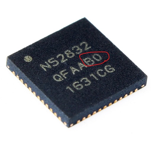
I then checked the ERRATA documentation for possible causes. Eventually, I noticed something related to IC revisions. To investigate further, I ordered different revisions (E0, E1, and G0). None of them worked. Surprisingly, only revision B0 — the one used in the XL52832 module — works properly on my PCB.

Could you please help me understand why revision B0 works on my PCB while the others do not? And more importantly, how can I resolve this issue so that my design is compatible with all revisions?

Best regards,

Parents
  • Hi,

    SDK 17.1.0 is compatible with all nRF52832 revisions (except for the Engineering revisions). It seems unlikely that the revision is what made the difference here, so I think debugging is needed to understand the issue.

    When you write that "ble_app_uart does not work", what exactly does that mean? How does it behave? How have you debugged, and what did you learn from debugging?

  • Hello ,


    I appreciate your support. I can successfully flash and run several BLE examples like ble_app_blinky, ble_app_cscs, and ble_app_bps. For these, I can connect via the nRF Connect app, control LEDs (e.g., turn them ON/OFF), and observe proper behavior, including the BLE connect LED indicating a successful connection.


    However, when I flash the ble_app_uart example, the device does not advertise. The BLE connect LED stays off, and during scanning with nRF Connect, the "NORDIC_UART" device does not appear.


    Troubleshooting Steps Taken:

    Hardware Verification: I inspected the board for potential faults (e.g., soldering issues, component placement), but found no obvious problems. Since other BLE examples work fine, the hardware seems functional for basic BLE operations.


    Debugging with Logs: To identify the failure point, I added NRF_LOG_INFO statements throughout the initialization in main.c and used the SEGGER RTT Viewer for output. Here's the modified code snippet for reference:


    // Initialize.

    NRF_LOG_INFO("Program started.");

    uart_init();

    NRF_LOG_INFO("UART initialized.");

    log_init();

    NRF_LOG_INFO("Log initialized.");

    timers_init();

    NRF_LOG_INFO("Timers initialized.");

    buttons_leds_init(&erase_bonds);

    NRF_LOG_INFO("Buttons and LEDs initialized.");

    power_management_init();

    NRF_LOG_INFO("Power management initialized.");

    ble_stack_init();

    NRF_LOG_INFO("BLE stack initialized.");

    gap_params_init();

    NRF_LOG_INFO("GAP params initialized.");

    gatt_init();

    NRF_LOG_INFO("GATT initialized.");

    services_init();

    NRF_LOG_INFO("Services initialized.");

    advertising_init();

    NRF_LOG_INFO("Advertising initialized.");

    conn_params_init();

    NRF_LOG_INFO("Connection params initialized.");


    // Start execution.

    printf("\r\nUART started.\r\n");

    NRF_LOG_INFO("Debug logging for UART over RTT started.");

    NRF_LOG_INFO("Advertising started.");

    advertising_start();


    // Enter main loop.

    for (;;)

    {

        idle_state_handle();

    }

    Initial RTT Output:

    00> <info> app: Program started.

    00>

    00> <info> app: UART initialized.

    00>

    00> <info> app: Log initialized.

    00>

    00> <info> app_timer: RTC: initialized.

    00>

    00> <info> app: Timers initialized.

    00>

    • <error> app: Fatal error.


    This suggests the crash occurs after timers_init() but before buttons_leds_init().

    Further Testing: I commented out the buttons_leds_init() call and its log statement to isolate the issue. The updated RTT output was:

    00> <info> app: Program started.

    00>

    00> <info> app: UART initialized.

    00>

    00> <info> app: Log initialized.

    00>

    00> <info> app_timer: RTC: initialized.

    00>

    00> <info> app: Timers initialized.

    00>

    00> <info> app: Power management initialized.

    00>

    00> <error> app: Fatal error

    00>

    Now the crash appears after power_management_init() but before ble_stack_init(). This points to a potential issue in ble_stack_init() when buttons_leds_init() is skipped.

    Configuration Changes: I modified sdk_config.h to change NRF_SDH_CLOCK_LF_SRC (e.g., switching between RC, XTAL, etc.), but this did not resolve the problem—the behavior remained the same.

    It is noteworthy that when I replaced the original nRF52832-QFAA-B0 chip with a new nRF52832-QFAA-E0 on the XL52832-D01 board, the behavior of the XL52832-D01, which had previously functioned correctly, changed and began exhibiting issues similar to those observed with my custom PCB.

    It seems initialization-related, possibly tied to SoftDevice enabling, clock configuration, or resource allocation. Any suggestions for capturing the specific error code (e.g., modifying app_error_handler) or other debugging steps would be greatly appreciated!

  • Hi,

    I am sorry, I was too fast when looking up the line number yesterday. This means that you are getting a UART framing error, as explain in this post. What is the state of the UART RX pin? Is it floating? Or if not, could there be a baud rate issue or baud rate mismatch? If so, it oculd be s simple as having an nRF device with ann HFINT that is on the edge. And in that case starting the HFXO when using UART could be usefull (it is also a good test). As a test, you could call sd_clock_hfclk_request() after initializing the SoftDevice to have the HFXO always running and see if that makes a difference.

  • Hi, thank you so much for your support.

    Step 1 – Clock Test (HFXO vs HFINT)
    I added sd_clock_hfclk_request(); after BLE stack initialization to force the HFXO (32 MHz crystal) to always run.
    My updated ble_stack_init() looks like this:

    static void ble_stack_init(void)
    {
        ret_code_t err_code;
    
        err_code = nrf_sdh_enable_request();
        APP_ERROR_CHECK(err_code);
    
        // Configure the BLE stack using the default settings.
        uint32_t ram_start = 0;
        err_code = nrf_sdh_ble_default_cfg_set(APP_BLE_CONN_CFG_TAG, &ram_start);
        APP_ERROR_CHECK(err_code);
    
        // Enable BLE stack.
        err_code = nrf_sdh_ble_enable(&ram_start);
        APP_ERROR_CHECK(err_code);
    
        // ⭐ Force HFXO on (for UART accuracy test)
        err_code = sd_clock_hfclk_request();
        APP_ERROR_CHECK(err_code);
    
        // Register a handler for BLE events.
        NRF_SDH_BLE_OBSERVER(m_ble_observer, APP_BLE_OBSERVER_PRIO, ble_evt_handler, NULL);
    }
    

    Result: No improvement, the same errors still occurred.

    Step 2 – Disabling Flow Control
    In pca10040.h I changed:

    #define HWFC false

    Result: No improvement, errors still occurred.

    Step 3 – Modifying Error Handling
    I modified the uart_event_handle() to avoid resetting the program on UART communication errors, and instead only print warnings:

    case APP_UART_COMMUNICATION_ERROR:
        NRF_LOG_WARNING("UART COMM ERROR: 0x%X", p_event->data.error_communication);
        break;
    
    case APP_UART_FIFO_ERROR:
        NRF_LOG_WARNING("UART FIFO ERROR: 0x%X", p_event->data.error_code);
        break;
    
    Result: After this change, the program continues to run and the BLE stack starts normally.
    RTT log output after changes
    :
    <info> app_timer: RTC: initialized.
    <warning> app: UART COMM ERROR: 0x4
    <warning> app: UART COMM ERROR: 0x8
    <info> app: HFXO requested
    <info> app: Debug logging for UART over RTT started.
    <info> app: Connected
    <info> app: Data len is set to 0xF4(244)
    
    The LED starts blinking, and the nRF Connect app shows NORDIC_UART and indicates a successful connection.

    Question:
    Could you please help me fully understand the root cause of these UART communication errors, and how I can properly solve it for my custom PCB?
    For reference, I am not using the TX/RX pins (#define RX_PIN_NUMBER 23, #define TX_PIN_NUMBER 24) on my board.

    Best wishes,

  • Hi,

    Avesta said:
    For reference, I am not using the TX/RX pins (#define RX_PIN_NUMBER 23, #define TX_PIN_NUMBER 24) on my board.

    Aha, so you do not have the UART pins connected, but have UART enabled so that the Rx pin is floating? Then this is something that coudl happen (the UART peripheral detects an input signal but it does not receive valid UART frame, resulting in framing error).. Disable the UART if not connected, or if you intent do keep it enabled, you could connect the Rx pin to VDD.

  • Hi,
    Thank you so much, Einar Thorsrud. By connecting the Rx pin to VDD, the problem is solved. Please advise me on how to disable the UART?

  • Hi,

    I am glad to hear you found the root cause of the problem.

    The ble_app_uart is intended to use UART, so it is qutie entageled in the code. But you can start by removing uart_init() and any calls and references to app_uart*. Also remember to remove the printf statement. And you would have to send/receive data some ohter way, as the way this sample is designed is to provide a way to tunnel UART via BLE.

Reply
  • Hi,

    I am glad to hear you found the root cause of the problem.

    The ble_app_uart is intended to use UART, so it is qutie entageled in the code. But you can start by removing uart_init() and any calls and references to app_uart*. Also remember to remove the printf statement. And you would have to send/receive data some ohter way, as the way this sample is designed is to provide a way to tunnel UART via BLE.

Children
Related