Do you agree that the following AI response is accurate? If so, I understand it to mean that I need 3 capacitors: one 68pF in series with each NFC trace and one 430pF in parallel with the NFC traces?
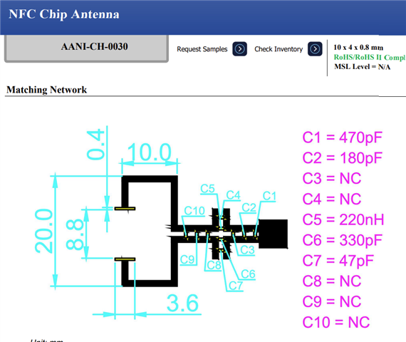
The AANI-CH-0030 NFC chip antenna from Abracon (inductance 0.298 µH, DCR 1.62 Ω, Q-factor 15.7 at 13.56 MHz, size 10 x 4 x 0.8 mm) can be used with the nRF54L15 NFCT (NFC Tag mode) by adding an external matching network to tune the resonant frequency to 13.56 MHz and match the chip's impedance.
Matching Network Topology The standard topology for Nordic NFCT pins (NFC1, NFC2) is:
- Two series capacitors (C_s1, C_s2) between the NFCT pins and the antenna ends to adjust impedance matching.
- One parallel capacitor (C_p) across the antenna ends to tune the resonant frequency.
- Schematic configuration:
- NFC1 -- C_s1 -- Antenna end 1
- NFC2 -- C_s2 -- Antenna end 2
- C_p between Antenna end 1 and end 2
- C_s1 = C_s2 = 68 pF (standard 0402 or 0603 ceramic, ±5% tolerance, e.g., Murata GRM1555C1H680JA01D)
- C_p = 430 pF (0402 or 0603 ceramic, ±5% tolerance, e.g., Murata GRM1555C1H431JA01D)
- Total effective capacitance C_total ≈ C_p + C_m + C_int ≈ 430 pF + 34 pF + 4 pF ≈ 468 pF (close to calculated 462 pF for resonance, with margin for tolerances).
- Resonant Frequency Formula: f = 1 / (2π √(L × C_total)), where L = 0.298 µH, f = 13.56 MHz = 13.56 × 10^6 Hz.
- Required C_total: C_total = 1 / (4π² f² L) = 1 / (4 × π² × (13.56e6)² × 0.298e-6) ≈ 462 pF (using omnicalculator.com/physics/resonant-frequency-lc or manual calculation).
- Effective Matching Capacitance (C_m): C_m = C_s / 2 (for C_s1 = C_s2 = C_s).
- Total C: C_total = C_p + C_m + C_int, where C_int ≈ 4 pF (nRF internal capacitance).
- Adjustments: For exact tuning, measure the assembled antenna impedance with a VNA (Vector Network Analyzer) and adjust C_p ±10% to achieve 13.56 MHz resonance and Q-factor ~20–30 for bandwidth. The AANI-CH-0030's low Q (15.7) limits efficiency, so aim for Q = 2πf L / R_a ≈ 15.7 (matches datasheet).
- The nRF54L15 NFCT is passive tag mode (NFC-A Listen), so the matching focuses on resonance at 13.56 MHz for reader power harvesting.
- No inductors needed in the matching network (the provided values are capacitor-only).
- Test for reading distance (~10–30 mm per Abracon datasheet) and adjust C_s for impedance (target ~50 Ω).
- For Altium, create a custom footprint for AANI-CH-0030 (10 x 4 mm) and add the network components in the schematic. Import BOM via Reports > Bill of Materials > Import.
- If C_int for nRF54L15 differs (check Nordic support or devzone.nordicsemi.com), recalculate C_p = 462 pF - C_int - (C_s / 2).