I can't control GPIO106 and 107

Dear nRF experts.

I am using the radio_test sample with SDK3.10

We used radio_test to add UART commands to control the on/off of all GPIOs for pin verification.
We found that GPIO106 and GPIO107 could not be turned on/off.
Do these two pins require any additional configuration?
I know the NFC pins require CONFIG_NFCT_PINS_AS_GPIOS=y.
But I don't understand why GPIO106 and GPIO107 are uncontrollable.
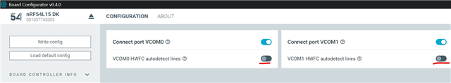
I used the nRF54L15 DK board for verification, and the same problem occurred.

Could you give me some suggestions?
Thanks.

Parents
  • Hello,

    What do you mean by "can't be turned off"? Does it mean that you are trying to disable them, but you measure it and it is still high/low? Or does it mean that you are not able to set it as high or low? 

    The P1.06 and P1.07 are by default the flow control pins for one of the UART of the nRF54L15. Particularly, it is the default UART HW Flow Control (hwfc) pins for uart20, which is used by default. 

    What you can do is to add this to your nrf54l15dk_nrf54l15.overlay:

    &pinctrl {
    	/omit-if-no-ref/ uart20_default: uart20_default {
    		group1 {
    			psels = <NRF_PSEL(UART_TX, 1, 4)>;
    		};
    
    		group2 {
    			psels = <NRF_PSEL(UART_RX, 1, 5)>;
    			bias-pull-up;
    		};
    	};
    
    	/omit-if-no-ref/ uart20_sleep: uart20_sleep {
    		group1 {
    			psels = <NRF_PSEL(UART_TX, 1, 4)>,
    				<NRF_PSEL(UART_RX, 1, 5)>;
    			low-power-enable;
    		};
    	};
    };
    
    
    &uart20 {
        status = "okay";
    	current-speed = <115200>;
    	pinctrl-0 = <&uart20_default>;
    	pinctrl-1 = <&uart20_sleep>;
    	pinctrl-names = "default", "sleep";
        /delete-property/ hw-flow-control;
    };

    This should make it not use these pins in uart20_default or uart20_sleep, and disable hw-flow-control from uart20.

    Note that if you are using a DK, the debugger still try to control the UART20 flow control pins. To disable this, use the Board Configurator tool in nRF Connect for Desktop:

    I am 90% sure it is the VCOM0, but try to disable VCOM1 as well if it doesn't work.

    Best regards,

    Edvin

  • Hi Edvin.

    Thank you very much for your reply.
    We're using the radio_radio sample code and have added an AT command, such as GPIO_TEST.
    When I send GPIO_TEST via UART,
    I set all GPIOs (excluding the TX and RX pins on the UART I'm using) to 1, then delay 200ms before setting them to 0. However, I've noticed that GPIO106 and GPIO107 don't seem to be set to 1 or 0.
    My overlay file is below.

    ....
            led13 {
                label = "led13";
                gpios = <&gpio1 6 0>;
            };
            led14 {
                label = "led14";
                gpios = <&gpio1 7 0>;
            };
            led15 {
                label = "led15";
                gpios = <&gpio1 8 0>;
            };
    ....

    How can I change the CTS and RTS modes of GPIO106 and 107 to general GPIO outputs in the overlay?

    We are a module manufacturer, so we have written a production test program to verify whether all module GPIOs are normal.

Reply
  • Hi Edvin.

    Thank you very much for your reply.
    We're using the radio_radio sample code and have added an AT command, such as GPIO_TEST.
    When I send GPIO_TEST via UART,
    I set all GPIOs (excluding the TX and RX pins on the UART I'm using) to 1, then delay 200ms before setting them to 0. However, I've noticed that GPIO106 and GPIO107 don't seem to be set to 1 or 0.
    My overlay file is below.

    ....
            led13 {
                label = "led13";
                gpios = <&gpio1 6 0>;
            };
            led14 {
                label = "led14";
                gpios = <&gpio1 7 0>;
            };
            led15 {
                label = "led15";
                gpios = <&gpio1 8 0>;
            };
    ....

    How can I change the CTS and RTS modes of GPIO106 and 107 to general GPIO outputs in the overlay?

    We are a module manufacturer, so we have written a production test program to verify whether all module GPIOs are normal.

Children
  • Sorry for the late reply. I was out of office yesterday.

    Did you include the part in my last reply to your overlay file?

    Is it possible to upload your entire application here, so that I can reproduce what you are seeing on a DK? Just zip the application folder that you are using, so that I can build and flash it to my DK.

    Best regards,

    Edvin

  • Hi Edvin.

    You can look at the settings of nrf54l15dk_nrf54l15_cpuapp.overlay.

    After powering up the nrf54L15, you can first execute the cansec_gpio_test command via UART. I'll set each GPIO to 1 and 0 once.
    Then observe whether GPIO106 and 107 change.

    radio_test_factory_3.10.zip

  • Try to uncomment this part of your nrf54l15dk_nrf54l15_cpuapp.overlay file:

    &uart20_sleep {
        group1 {
            psels = <NRF_PSEL(UART_TX, 1, 4)>,
                    <NRF_PSEL(UART_RX, 1, 5)>;
            low-power-enable;
        };
    };

    I didn't test the UART command, but I added this to the main() and right before the main() function in main.c:

    #define LED13_NODE DT_PATH(leds, led13)
    #define LED14_NODE DT_PATH(leds, led14)
    static const struct gpio_dt_spec myled13 = GPIO_DT_SPEC_GET(LED13_NODE, gpios);
    static const struct gpio_dt_spec myled14 = GPIO_DT_SPEC_GET(LED14_NODE, gpios);
    
    void test_gpio_13_14(void)
    {
    	int ret;
    
    	if (!gpio_is_ready_dt(&myled13)) 
    	{
    		return;
    	}
    	ret = gpio_pin_configure_dt(&myled13, GPIO_OUTPUT_ACTIVE);
    	if (ret < 0) 
    	{
    		return;
    	}
    
    	if (!gpio_is_ready_dt(&myled14)) 
    	{
    		return;
    	}
    	ret = gpio_pin_configure_dt(&myled14, GPIO_OUTPUT_ACTIVE);
    	if (ret < 0) 
    	{
    		return;
    	}
    
    	gpio_pin_set(myled13.port, myled13.pin, 1);
    	gpio_pin_set(myled14.port, myled14.pin, 1);
    	k_sleep(K_MSEC(1000));
    	gpio_pin_set(myled13.port, myled13.pin, 0);
    	gpio_pin_set(myled14.port, myled14.pin, 0);
    }
    
    int main(void)
    {
    	printk("Starting Radio Test sample\n");
    
    	test_gpio_13_14();
    
    	clock_init();
    	...

    And when I uncommented the uart20_sleep in the .overlay file, it worked as intended:

    (these are pins P1.06 and P1.07)

    For reference, here is the entire, modified application project:

    radio_test_f.zip 

    Best regards,

    Edvin

Related