I’m working on a project using the nRF54L15 SoC together with the nPM1300 Power Management IC.
In my hardware setup:
-
BUCK2 output from the nPM1300 is connected to the LSIN1 pin.
-
The LSOUT1 pin powers an I²C sensor.
The goal is to dynamically turn the sensor power on/off from firmware by controlling the Load Switch 1 (LDSW1) via I²C, not via the GPIO control pins. I’m using the load switch mode instead of the LDO mode, because the LDO mode supports up to 50 mA, while the load switch mode supports up to 100 mA — which better suits the sensor’s power requirements.
I’ve configured the nPM1300 in the Devicetree as an I²C peripheral and defined the npm1300_ldsw1 regulator node:
#include <dt-bindings/regulator/npm1300.h>
#include <zephyr/dt-bindings/input/input-event-codes.h>

&pinctrl {
    i2c22_default: i2c22_default {
        group1 {
            psels = <NRF_PSEL(TWIM_SDA, 1, 12)>,
                    <NRF_PSEL(TWIM_SCL, 1, 11)>;
        };
    };
    i2c22_sleep: i2c22_sleep {
        group1 {
            psels = <NRF_PSEL(TWIM_SDA, 1, 12)>,
                    <NRF_PSEL(TWIM_SCL, 1, 11)>;
            low-power-enable;
        };
    };
};

&i2c22 {
    status = "okay";
    pinctrl-0 = <&i2c22_default>;
    pinctrl-1 = <&i2c22_sleep>;
    pinctrl-names = "default", "sleep";


    sht4x: sht4x@44 {
        status = "okay";
        compatible = "sensirion,sht4x";
        reg = <0x44>;
        repeatability = <0>;
    };

    scd41@62 {
        compatible = "sensirion,scd41";
        reg = <0x62>;
        status = "okay";
    };


    npm1300: pmic@6b {
        compatible = "nordic,npm1300";
        reg = <0x6b>;

        npm1300_gpios: gpio-controller {
            compatible = "nordic,npm1300-gpio";
            gpio-controller;
            #gpio-cells = <2>;
            ngpios = <5>;
            status = "disabled";
        };

        npm1300_regulators: npm1300_regulators {
            compatible = "nordic,npm1300-regulator";
            status = "okay";

            npm1300_buck1: BUCK1 {
                status = "okay";
                regulator-min-microvolt = <1000000>;
                regulator-max-microvolt = <3300000>;
                regulator-init-microvolt =  <1800000>;
                retention-microvolt = <1200000>;
            };

            npm1300_buck2: BUCK2 {
                status = "okay";
                regulator-min-microvolt = <1000000>;
                regulator-max-microvolt = <3300000>;
                regulator-init-microvolt =  <3300000>;
                retention-microvolt = <1800000>;
            };

            /* Load switches */
            npm1300_ldsw1: LDO1 {
                status = "okay";
                regulator-min-microvolt = <1000000>;
                regulator-max-microvolt = <3300000>;
                regulator-initial-mode = <NPM1300_LDSW_MODE_LDSW>;
            };

            npm1300_ldsw2: LDO2 {
                status = "disabled";
                regulator-min-microvolt = <3300000>;
                regulator-max-microvolt = <3300000>;
                regulator-initial-mode = <NPM1300_LDSW_MODE_LDSW>;
            };
        };

        /*
        npm1300_charger: charger {
            compatible = "nordic,npm1300-charger";
            term-microvolt = <4150000>;
            current-microamp = <150000>;
            dischg-limit-microamp = <1000000>;
            vbus-limit-microamp = <500000>;
            thermistor-ohms = <10000>;
            thermistor-beta = <3380>;
            charging-enable;
            status = "okay";
        };
        */

        npm1300_leds: leds {
            compatible = "nordic,npm1300-led";
            nordic,led0-mode = "error";
            nordic,led1-mode = "charging";
            nordic,led2-mode = "host";
        };
    };
};
And current my main.c:
#include <zephyr/kernel.h>
#include <zephyr/device.h>
#include <zephyr/drivers/regulator.h>
#include <zephyr/drivers/sensor.h>
#include <zephyr/logging/log.h>
LOG_MODULE_REGISTER(main_app, LOG_LEVEL_INF);
void main(void)
{
const struct device *sht_dev = DEVICE_DT_GET(DT_NODELABEL(sht4x));
const struct device *ldsw1 = DEVICE_DT_GET(DT_NODELABEL(npm1300_ldsw1));
struct sensor_value temp, humidity;
int ret;
if (!device_is_ready(ldsw1)) {
LOG_ERR("LOADSW1 device not ready");
return;
}
if (!device_is_ready(sht_dev)) {
LOG_ERR("SHT4x device not ready");
return;
}
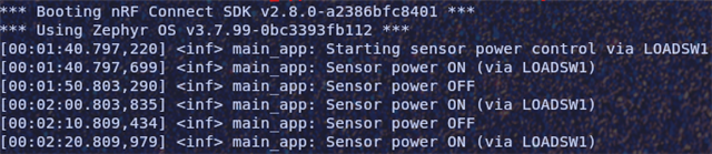
LOG_INF("Starting sensor power control via LOADSW1");
while (1) {
/* Turn on sensor power */
if (!regulator_is_enabled(ldsw1))
ret = regulator_enable(ldsw1);
if (ret) {
LOG_ERR("Failed to enable LOADSW1: %d", ret);
k_sleep(K_SECONDS(10));
continue;
}
LOG_INF("Sensor power ON (via LOADSW1)");
k_sleep(K_MSEC(5)); // settle time
ret = sensor_sample_fetch(sht_dev);
if (!ret) {
sensor_channel_get(sht_dev, SENSOR_CHAN_AMBIENT_TEMP, &temp);
sensor_channel_get(sht_dev, SENSOR_CHAN_HUMIDITY, &humidity);
LOG_INF("Temp: %d.%06d C, RH: %d.%06d%%",
temp.val1, temp.val2, humidity.val1, humidity.val2);
} else {
LOG_ERR("Sensor read failed: %d", ret);
}
k_sleep(K_SECONDS(10));
/* Power off sensor */
if (regulator_is_enabled(ldsw1))
ret = regulator_disable(ldsw1);
if (ret) {
LOG_ERR("Failed to disable LOADSW1: %d", ret);
k_sleep(K_SECONDS(10));
continue;
}
LOG_INF("Sensor power OFF");
k_sleep(K_SECONDS(10));
}
}
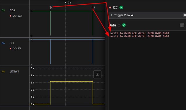
However, the LSOUT1 pin always remains at 3.3 V. I’d like to confirm whether the current nPM1300 Zephyr driver supports controlling the load switch (LDSW) via I²C instead of GPIO, or if I’m missing something in my configuration.