RayTac mdbt42q-p512kv2 programming issue with custom board

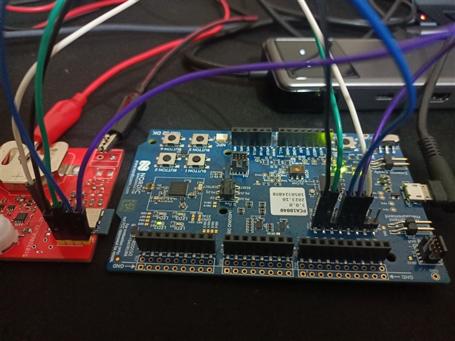
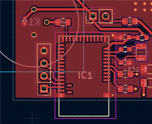
I'm trying to program a custom board with a Raytac nRF52832 module using the nRF52 DK's onboard J-Link via the P20 debug out port. The J-Link only detects the onboard nRF52832, not my external module.

I've checked the following:

  • My custom board is powered with a solid 3V.
  • The module's DEC4 pin shows 1.234V, so its internal regulator is working.
  • All P20 connections (GND, SWDCLK, SWDIO, RESET) are wired correctly per the DK user guide.
  • The P20 VTG pin is correctly connected to my board's 3V supply.
  • The P19 debug out port is completely empty.

To verify my board, I connected an ST-Link v2 with OpenOCD, and it successfully detected the chip. The log shows:

❯ openocd -f interface/stlink.cfg -f target/nrf52.cfg
Open On-Chip Debugger 0.12.0
Licensed under GNU GPL v2
For bug reports, read
Info : auto-selecting first available session transport "hla_swd". To override use 'transport select <transport>'.
Info : The selected transport took over low-level target control. The results might differ compared to plain JTAG/SWD
nRF52 device has a CTRL-AP dedicated to recover the device from AP lock.
A high level adapter (like a ST-Link) you are currently using cannot access
the CTRL-AP so 'nrf52_recover' command will not work.
Do not enable UICR APPROTECT.
Info : Listening on port 6666 for tcl connections
Info : Listening on port 4444 for telnet connections
Info : clock speed 1000 kHz
Info : STLINK V2J45M31 (API v2) VID:PID 0483:374B
Info : Target voltage: 3.263684
Info : [nrf52.cpu] Cortex-M4 r0p1 processor detected
Info : [nrf52.cpu] target has 6 breakpoints, 4 watchpoints
Info : starting gdb server for nrf52.cpu on 3333
Info : Listening on port 3333 for gdb connections
Questions:
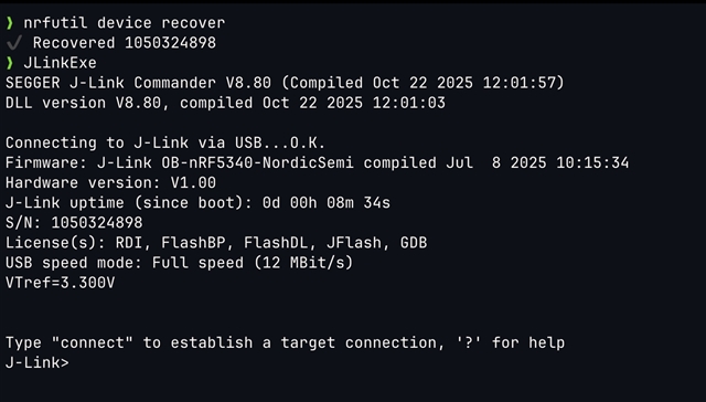
  1. Since the ST-Link works, is there a special
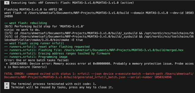
 nrfjprog or nrfutil command other then "recover" needed to force the DK's J-Link to use the P20 port? I tried vs code board recover and nrf tool recovering but it did not help.
  2. If I give up on the DK, will a J-Link EDU Mini work correctly with a 3V (not 3.3V) target board? I will buy j-link edu if it will work.
  3. Can I recover chip with using ST-link?

Document1-20251104125702.pdf

  • Hi, 

    My custom board is powered with a solid 3V.

    Do you power both your cusbom board and the nRF52DK? 

    What is the detected VTref value when you open the J-Link Commander?

    All P20 connections (GND, SWDCLK, SWDIO, RESET) are wired correctly per the DK user guide.

    Check this post.

    is there a special nrfjprog or nrfutil command other then "recover" needed to force the DK's J-Link to use the P20 port? I tried vs code board recover and nrf tool recovering but it did not help.

    Please run "nrfutil self-upgrade" and "nrfutil upgrade" to upgrade nrfutil and nrfutil device versions, then execute "nrfutil version" and "nrfutil list" to check they are the latest version nrfutil 8.1.1 and device 2.15.1. Now, you can run "nrfutil device recover". If it still cannot help, please provide the log. 

    If I give up on the DK, will a J-Link EDU Mini work correctly with a 3V (not 3.3V) target board? I will buy j-link edu if it will work.

    Yes, here is a use case  Error -160 on nrfjprog when verify nrf52840 using J-Link EDU Mini for nRF52840, but I think it also applies to nRF52832. 

    Can I recover chip with using ST-link?

    We don't test with ST-Link, and we are not familiar with ST-Link. 

    Regards,
    Amanda H.

  • I have an update on my issue. I successfully managed to program my custom Raytac board using an ST-Link v2 and OpenOCD.

    I was able to erase the chip with this command:
    openocd -f interface/stlink.cfg -f target/nrf52.cfg -c "init" -c "halt" -c "nrf5 mass_erase" -c "reset exit"

    And I successfully flashed my merged.hex file with this command:
    openocd -f interface/stlink.cfg -f target/nrf52.cfg -c "program merged.hex verify reset exit"

    For my prj.conf, I'm using these clock settings:
    CONFIG_CLOCK_CONTROL_NRF_K32SRC_RC=y
    CONFIG_CLOCK_CONTROL_NRF_K32SRC_500PPM=y
    CONFIG_CLOCK_CONTROL_NRF_K32SRC_RC_CALIBRATION=y
    CONFIG_CLOCK_CONTROL_NRF_CALIBRATION_LF_ALWAYS_ON=y

    I used these lines because my board does not have an external crystal oscillator and I must use the internal RC oscillator.

    I still don't know why the onboard J-Link on my nRF52 DK wouldn't work, even with the P19 port empty. If you see any mistake I might have made in my DK setup, please let me know. It's a bit difficult to debug this way (with OpenOCD) since there is no Virtual COM port.

    Thanks for help in advance.

  • You can refer to this post for the connection and check by the J-Link Commander, also answer the questions in my previous reply. Please also provide a picture to show how you connect the custom board to the nRF52 DK.  

  • Here is JlinkExe and "nrfutils device recover" outputs:

    And here is my connections:

    Here is my PCB layout:

    The component between VBATT and VDD is 0R resistor. I guess this should be a problem.

    Here is flashing log:

    I checked VTG pin with a multimeter and my custom board correctly provide 3 volts.

    Thanks you for you support I hope this will be enough to diagnose my problem. 

  • Could you run

    set NRFUTIL_LOG=trace
    west flash (or whatever invocation you used)

    in a terminal in vscode, and then send the log from <USERHOME>/.nrfutil/logs/nrfutil-device.log?

    via 

Related