Slow GPIO Output Speed Issue: Inquiring About Causes and Solutions

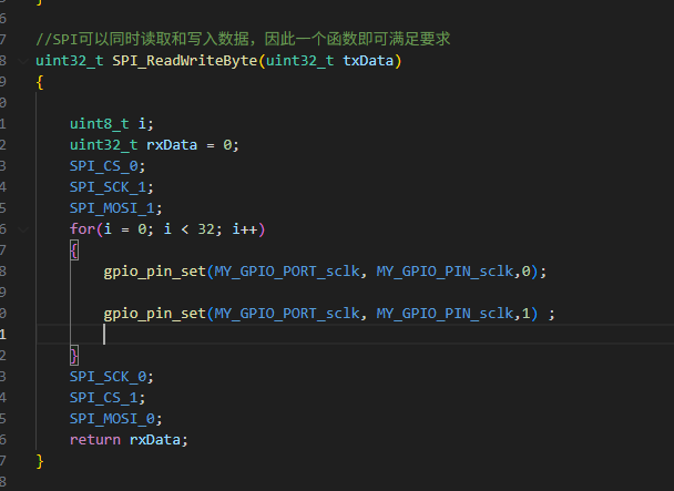
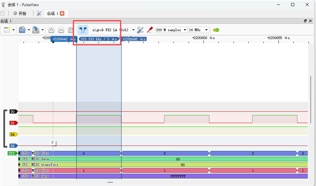
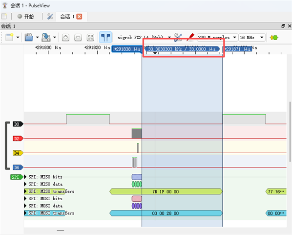
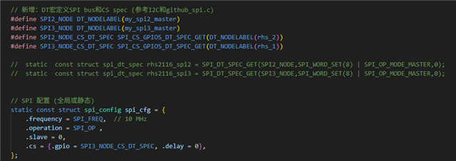
Hello, we are currently testing the output of square waves through GPIO output pins. However, I found that a single operation to set the GPIO output pin high or low using the gpio_pin_set function takes about 3 microseconds, so the transmitted square wave does not meet our speed requirements. I would like to know what is causing the slow GPIO output speed—is it the internal clock being too slow? Or too many parallel tasks? (In debug mode, the chip does not jump to other tasks and executes GPIO operations continuously.) Are there better GPIO configuration functions? Please provide us with assistance.

Parents
  • Hi,


    1. include header hal/nrf_gpio.h and use nrf_gpio_pin_set / clear functions. These will write directly to the register.

    2. In addition; Try adding a barrier or a readback of an event register.

    Reading back for instance (void)NRF_TIMER2->EVENTS_COMPARE[0]; between each gpio_pin_set function call will generate a PCLK16M wait state, thus you will ensure that the gpio is set/clr with a higher accuracy/speed.


    Kind regards,

    Håkon

  • We followed your suggestion to directly write to the registers using the nrf_gpio_pin_set / clear functions, which improved the clock speed of our simulated SPI, but it's still insufficient. Therefore, I defined a timer interrupt function void TIMER2_IRQHandler(void) in an attempt to control the clock frequency myself. Although the program can run, according to the logic analyzer, this timer interrupt is not enabled. We currently have two hypotheses: first, there is no external clock source HFCLK; second, the timer2 timer is not triggering. Here are my current main file, configuration file, and device tree file. Could you please help me analyze the reason?

    /*
     * Copyright (c) 2018 Nordic Semiconductor ASA
     *
     * SPDX-License-Identifier: LicenseRef-Nordic-5-Clause
     */
    
    /** @file
     *  @brief Nordic UART Bridge Service (NUS) sample
     */
    #include <uart_async_adapter.h>
    
    #include <zephyr/types.h>
    #include <zephyr/kernel.h>
    #include <zephyr/drivers/uart.h>
    #include <zephyr/usb/usb_device.h>
    
    #include <zephyr/device.h>
    #include <zephyr/devicetree.h>
    #include <soc.h>
    
    #include <zephyr/bluetooth/bluetooth.h>
    #include <zephyr/bluetooth/uuid.h>
    #include <zephyr/bluetooth/gatt.h>
    #include <zephyr/bluetooth/hci.h>
    
    #include <bluetooth/services/nus.h>
    
    #include <dk_buttons_and_leds.h>
    
    #include <zephyr/settings/settings.h>
    
    #include <stdio.h>
    #include <string.h>
    
    #include <zephyr/logging/log.h>
    
    #include <zephyr/drivers/gpio.h>
    #include<zephyr/sys/printk.h>
    #include<zephyr/drivers/clock_control.h>
    #include<zephyr/drivers/clock_control/nrf_clock_control.h>
    
    #include <zephyr/drivers/i2c.h>
    #include <zephyr/devicetree.h>
    
    #include <zephyr/drivers/regulator.h>
    #include <nrfx.h>
    #include<zephyr/drivers/spi.h>
    
    #include<hal/nrf_gpio.h>
    
    #include<nrfx_timer.h>


    #define LOG_MODULE_NAME peripheral_uart
    LOG_MODULE_REGISTER(LOG_MODULE_NAME);
    
    #define STACKSIZE CONFIG_BT_NUS_THREAD_STACK_SIZE
    #define PRIORITY 7
    
    #define DEVICE_NAME CONFIG_BT_DEVICE_NAME
    #define DEVICE_NAME_LEN	(sizeof(DEVICE_NAME) - 1)
    
    #define RUN_STATUS_LED DK_LED1
    #define RUN_LED_BLINK_INTERVAL 1000
    
    #define CON_STATUS_LED DK_LED2
    
    #define KEY_PASSKEY_ACCEPT DK_BTN1_MSK
    #define KEY_PASSKEY_REJECT DK_BTN2_MSK
    
    #define UART_BUF_SIZE CONFIG_BT_NUS_UART_BUFFER_SIZE
    #define UART_WAIT_FOR_BUF_DELAY K_MSEC(50)
    #define UART_WAIT_FOR_RX CONFIG_BT_NUS_UART_RX_WAIT_TIME
    
    
    //* I2C 初始化 (参考Nordic指南:使用DT宏获取spec) */
    #define I2C_NODE DT_NODELABEL(lt3582)  /* 引用overlay标签 */
    
    
    #define RHS_CHIP_ID 32  // ROM reg 255
    
    // 寄存器地址
    #define REG_ADC_BIAS 0
    #define REG_DSP_CTRL 1
    #define REG_ZCHECK_CTRL 2
    #define REG_ZCHECK_DAC 3
    #define REG_RH1_SEL 4
    #define REG_RH2_SEL 5
    #define REG_RL_A_SEL 6
    #define REG_RL_B_SEL 7
    #define REG_AC_AMP_POWER 8
    #define REG_FAST_SETTLE 10
    #define REG_AMP_FL_SEL 12
    #define REG_STIM_STEP 34
    #define REG_STIM_BIAS 35
    #define REG_CL_RECOV_V 36
    #define REG_CL_RECOV_I 37
    #define REG_DC_AMP_POWER 38
    #define REG_COMP_MON 40
    #define REG_STIM_EN_A 42  // 刺激使能 A
    #define REG_STIM_EN_B 43  // 刺激使能 B
    #define REG_STIM_ON 44
    #define REG_STIM_POL 45
    #define REG_CHARGE_REC_SW 46
    #define REG_CL_RECOV_EN 48
    #define REG_FAULT_CURR 50
    
    // 初始化值 (手册 page 45, 30 kS/s, 7.5 kHz fH, 5 Hz fL)
    #define INIT_ADC_BIAS 0x00C5  // MUX/ADC bias for 480 kS/s
    #define INIT_DSP_CTRL 0x051A  // DSP 4.665 Hz, absmode=0, twoscomp=0
    #define INIT_RH1_SEL 0x0016
    #define INIT_RH2_SEL 0x0017
    #define INIT_RL_A_SEL 0x00A8  // 5 Hz
    #define INIT_RL_B_SEL 0x000A  // 1 kHz alternate
    #define INIT_AC_POWER 0xFFFF
    #define INIT_DC_POWER 0xFFFF  // 重要:全开,避免 bug
    #define INIT_FAST_SETTLE 0x0000
    #define INIT_AMP_FL_SEL 0xFFFF  // 全用 A (5 Hz)
    #define INIT_STIM_STEP 0x00E2   // 1 uA/step
    #define INIT_STIM_BIAS 0x00AA
    #define INIT_CL_V 0x0080        // 0V
    #define INIT_CL_I 0x4F00        // 1 nA
    #define INIT_STIM_EN_A 0x0000   // 禁用刺激
    #define INIT_STIM_EN_B 0x0000
    #define INIT_STIM_ON 0x0000
    #define INIT_STIM_POL 0x0000    // 负极性
    #define INIT_CHARGE_REC_SW 0x0000
    #define INIT_CL_EN 0x0000
    
    /* 手动定义:GPIO 端口(nRF5340 默认 gpio0)和引脚号 */
    #define MY_GPIO_PORT_cs DEVICE_DT_GET(DT_NODELABEL(gpio0))  // 获取 gpio0 端口指针
    #define MY_GPIO_PIN_cs ((gpio_pin_t)15U)  // 自定义引脚 P0.14(uint32_t 类型)
    
    /* 手动定义:GPIO 端口(nRF5340 默认 gpio0)和引脚号 */
    #define MY_GPIO_PORT_sclk DEVICE_DT_GET(DT_NODELABEL(gpio0))  // 获取 gpio0 端口指针
    #define MY_GPIO_PIN_sclk ((gpio_pin_t)14U)  // 自定义引脚 P0.14(uint32_t 类型)
    
    /* 手动定义:GPIO 端口(nRF5340 默认 gpio0)和引脚号 */
    #define MY_GPIO_PORT_mosi DEVICE_DT_GET(DT_NODELABEL(gpio0))  // 获取 gpio0 端口指针
    #define MY_GPIO_PIN_mosi ((gpio_pin_t)16U)  // 自定义引脚 P0.14(uint32_t 类型)
    
    /* 手动定义:GPIO 端口(nRF5340 默认 gpio0)和引脚号 */
    #define MY_GPIO_PORT_miso DEVICE_DT_GET(DT_NODELABEL(gpio0))  // 获取 gpio0 端口指针
    #define MY_GPIO_PIN_miso ((gpio_pin_t)17U)// 自定义引脚 P0.14(uint32_t 类型)


    // #define SPI_CS_1    gpio_pin_set(MY_GPIO_PORT_cs, MY_GPIO_PIN_cs,1)            /* SCK = 1 */
    // #define SPI_CS_0    gpio_pin_set(MY_GPIO_PORT_cs, MY_GPIO_PIN_cs,0)   
    
    // #define SPI_SCK_1    gpio_pin_set(MY_GPIO_PORT_sclk, MY_GPIO_PIN_sclk,1)            /* SCK = 1 */
    // #define SPI_SCK_0    gpio_pin_set(MY_GPIO_PORT_sclk, MY_GPIO_PIN_sclk,0)        /* SCK = 0 */
    
    
    // #define SPI_MOSI_1     gpio_pin_set(MY_GPIO_PORT_mosi, MY_GPIO_PIN_mosi,1)           /* MOSI = 1 */
    // #define SPI_MOSI_0     gpio_pin_set( MY_GPIO_PORT_mosi, MY_GPIO_PIN_mosi,0)        /* MOSI = 0 */
    
    // #define SPI_READ_MISO    gpio_pin_get(MY_GPIO_PORT_miso, MY_GPIO_PIN_miso)    /* 读MISO口线状态 */
    
    //#define Dummy_Byte    0xFF    //读取时MISO发送的数据,可以为任意数据


    #define SPI_CS_1    nrf_gpio_pin_set( MY_GPIO_PIN_cs)            /* SCK = 1 */
    #define SPI_CS_0    nrf_gpio_pin_clear(MY_GPIO_PIN_cs)   
    
    #define SPI_SCK_1    nrf_gpio_pin_set(MY_GPIO_PIN_sclk)            /* SCK = 1 */
    #define SPI_SCK_0    nrf_gpio_pin_clear(MY_GPIO_PIN_sclk)        /* SCK = 0 */
    
    
    #define SPI_MOSI_1     nrf_gpio_pin_set(MY_GPIO_PIN_mosi)           /* MOSI = 1 */
    #define SPI_MOSI_0     nrf_gpio_pin_clear(MY_GPIO_PIN_mosi)        /* MOSI = 0 */
    
    #define SPI_READ_MISO    nrf_gpio_pin_read( MY_GPIO_PIN_miso)    /* 读MISO口线状态 */
    
    //static nrfx_timer_t timer2 = NRFX_TIMER_INSTANCE(2);
    
    //初始化SPI
    void SPI_IoInit(void)
    {
       
        /* 配置输出引脚:CS, SCK, MOSI 为输出,默认高电平 */
        nrf_gpio_cfg_output(MY_GPIO_PIN_cs);
        nrf_gpio_cfg_output(MY_GPIO_PIN_sclk);
        nrf_gpio_cfg_output(MY_GPIO_PIN_mosi);
    
        /* 配置输入引脚:MISO 为输入,无上拉/下拉 */
        nrf_gpio_cfg_input(MY_GPIO_PIN_miso, NRF_GPIO_PIN_NOPULL);
    
    
    // const struct device *gpio_port = DEVICE_DT_GET(DT_NODELABEL(gpio0));
    // if (!gpio_port || !device_is_ready(gpio_port)) {
    //     LOG_ERR("GPIO_0 binding failed or not ready");
    //     //goto ble_init;
    // }
    // LOG_INF("GPIO_0 ready %p", (void*)gpio_port);
    
    // struct gpio_dt_spec cs1 = {
    //     .port = gpio_port,
    //     .pin = 15,
    //     //.pin = 6,
    //     .dt_flags = 0,
    //    //.dt_flags = GPIO_ACTIVE_LOW,
    // };
    // gpio_pin_configure_dt(&cs1, GPIO_OUTPUT_ACTIVE);
    
    // struct gpio_dt_spec sck1 = {
    //     .port = gpio_port,
    //     .pin = 14,
    //     //.pin = 6,
    //     .dt_flags = 0,
    //    //.dt_flags = GPIO_ACTIVE_LOW,
    // };
    // gpio_pin_configure_dt(&sck1, GPIO_OUTPUT_ACTIVE);
    
    // struct gpio_dt_spec mosi1 = {
    //     .port = gpio_port,
    //     .pin = 16,
    //     //.pin = 6,
    //     .dt_flags = 0,
    //    //.dt_flags = GPIO_ACTIVE_LOW,
    // };
    // gpio_pin_configure_dt(&mosi1, GPIO_OUTPUT_ACTIVE);
    
    // struct gpio_dt_spec miso1 = {
    //     .port = gpio_port,
    //     .pin = 17,
    //     //.pin = 6,
    //     .dt_flags = 0,
    //    //.dt_flags = GPIO_ACTIVE_LOW,
    // };
    // gpio_pin_configure_dt(&miso1, GPIO_INPUT );
    
    // struct gpio_dt_spec scl1 = {
    //     .port = gpio_port,
    //     .pin = 24,
    //     //.pin = 6,
    //     .dt_flags = 0,
    //    //.dt_flags = GPIO_ACTIVE_LOW,
    // };
    // gpio_pin_configure_dt(&scl1, GPIO_OUTPUT_ACTIVE);
    
    
        SPI_CS_1;
        SPI_SCK_1;
        k_sleep(K_MSEC(10));
        SPI_MOSI_0;
       // SPI_READ_MISO;
        
    }
    static volatile uint32_t spi_tx_data = 0;
    static volatile uint32_t spi_rx_data = 0;
    static volatile uint8_t spi_bit_pos = 0;
    static volatile bool spi_state = false;  // false: prep (falling), true: sample (rising)
    static volatile bool spi_transfer_complete = false;
    
    //SPI可以同时读取和写入数据,因此一个函数即可满足要求
    uint32_t SPI_ReadWriteByte(uint32_t txData)
    {
      // 初始化状态
        spi_rx_data = 0;
        spi_bit_pos = 0;
        spi_state = false;
        spi_transfer_complete = false;
        spi_tx_data=txData;
        
        // CS low, initial SCK low, MOSI idle (will be set in first prep)
        SPI_CS_0;
        SPI_SCK_0;
        SPI_MOSI_0;  // Idle low
    
      // 手动寄存器:设置 CC[0]=1 + SHORTS(自动清零)+ 中断使能 + 启动
        NRF_TIMER2->CC[0] = 1;                         // CC[0]=1 (125ns interval, 8 MHz events)
        NRF_TIMER2->SHORTS = (1UL << 0);               // SHORTS_COMPARE0_CLEAR (位0: 清零计数器)
        NRF_TIMER2->INTENSET = (1UL << 0);             // INTENSET_COMPARE0 (位0: 启用中断)
        NRF_TIMER2->TASKS_CLEAR = 1UL;                 // 清零计数器
        NRF_TIMER2->TASKS_START = 1UL;                 // 启动定时器
    
        // 等待传输完成(添加超时调试:避免无限挂)
        uint32_t timeout = 0;
        while (!spi_transfer_complete && timeout < 1000000) {  // ~1s 超时(调试用)
            __NOP();
            timeout++;
        }
        if (timeout >= 1000000) {
            printk("SPI timeout! bit_pos=%d\n", spi_bit_pos);  // 调试:检查 ISR 执行
        }
    
      // 手动寄存器:停止定时器 + 清除
        NRF_TIMER2->TASKS_STOP = 1UL;                  // 停止
        NRF_TIMER2->TASKS_CLEAR = 1UL;                 // 清零
        NRF_TIMER2->INTENCLR = (1UL << 0);             // 禁用中断
      
    
        // CS high, SCK low, MOSI low
        SPI_SCK_0;
        SPI_CS_1;
        SPI_MOSI_0;
    
        return spi_rx_data;
    
    
        // uint8_t i;
        // uint32_t rxData = 0;
        // SPI_CS_0;
        // SPI_SCK_1;
        // SPI_MOSI_1;
        // for(i = 0; i < 32; i++)
        // {
        //     SPI_SCK_0;
        //     //k_usleep(1);
        //     //数据发送
        //     if(txData & 0x80000000){
        //         SPI_MOSI_1;
        //     }else{
        //         SPI_MOSI_0;
        //     }
        //     txData <<= 1;
        //     //k_usleep(1);
        //     //k_sleep(K_USEC(1));
        //     //SPI_SCK_0;
        //     SPI_SCK_1;
        //     //k_usleep(1);
        //     //k_sleep(K_USEC(1));
        //     //数据接收
        //     rxData <<= 1;
        //     if(SPI_READ_MISO){
        //        rxData |= 0x01;
        //     }
            
        //     //k_usleep(1);
        //     // k_sleep(K_USEC(1));
        // }
        // SPI_SCK_0;
        // SPI_CS_1;
        // SPI_MOSI_0;
        // return rxData;
    }
    
    void TIMER2_IRQHandler(void)
    {
        if (NRF_TIMER2->EVENTS_COMPARE[0]) {
            NRF_TIMER2->EVENTS_COMPARE[0] = 0;  // 清除事件
    
            if (spi_bit_pos < 32) {
                if (!spi_state) {
                    // Prep phase (falling edge): Set MOSI for next bit, SCK low
                    SPI_SCK_0;
                    uint32_t tx_bit = (spi_tx_data >> (31 - spi_bit_pos)) & 1UL;
                    if (tx_bit) {
                        SPI_MOSI_1;
                    } else {
                        SPI_MOSI_0;
                    }
                    spi_bit_pos++;
                    spi_state = true;  // Next: rising
                } else {
                    // Sample phase (rising edge): Sample MISO, SCK high
                    SPI_SCK_1;
                    uint32_t miso_bit = SPI_READ_MISO;
                    spi_rx_data |= (miso_bit << (31 - (spi_bit_pos - 1)));  // Shift into MSB first
                    spi_state = false;  // Next: prep
                }
            } else if (spi_bit_pos == 32) {
                // Transfer done: extra tick to finalize
                SPI_SCK_0;
                spi_transfer_complete = true;
                spi_bit_pos++;  // Prevent re-entry
            }
        }
    }
    
    uint32_t SPI_ReadByte(uint32_t rxData)
    {
        uint32_t answer;
        answer=SPI_ReadWriteByte(rxData);
        return answer;
    }
    
    void SPI_WriteByte(uint32_t txData)
    {
        (void)SPI_ReadWriteByte(txData);
    }
    
    
    static struct rhs2116_dev rhs1;
    static struct rhs2116_dev rhs2;
    
    static int16_t samples[32];
    
    static	uint8_t data_buffer[194];  // 累计缓冲: 3 次采样 * 64B = 192B+包头+包序列号
    static	uint8_t counter = 0;  // 采样计数器 (0-2)
    
    // SPI 配置
    // #define SPI_FREQ DT_PROP(DT_NODELABEL(spi3), spi_max_frequency)  // 10 MHz
    // #define SPI_OP SPI_WORD_SET(8) | SPI_OP_MODE_MASTER | SPI_MODE_CPOL0 | SPI_MODE_CPHA0
    
    #define SPI_FREQ (8000000U)  // 10 MHz
    #define SPI_OP (SPI_WORD_SET(8) | SPI_OP_MODE_MASTER)  // Mode 0: CPOL=0, CPHA=0
    
    static uint8_t ble_ADC[250];
    static uint8_t ble_Tx[250];
    //static uint8_t ble_Tx1[250];
    static uint16_t bag=0;
    static uint16_t LASTbag=0;
    //static int8_t counter=0;
    static struct k_timer adc_timer;  // 定时器实例
    static void adc_timer_handler(struct k_timer *timer_id);  // 前向声明
    static struct k_work adc_work ;
    
    #define LED0_NODE DT_ALIAS(led0)
    static const struct gpio_dt_spec led = GPIO_DT_SPEC_GET(DT_ALIAS(led0), gpios);
    
    static void exchange_func(struct bt_conn *conn, uint8_t att_err, struct bt_gatt_exchange_params *params);
    
    #define BLE_NUS_THROUGHPUT_MAX
    #define BLE_NUS_THROUGHPUT_TEST
    
    #if defined(BLE_NUS_THROUGHPUT_MAX)
    static K_SEM_DEFINE(nus_connection_sem,0,1);
    static const char*phy2str(uint8_t phy)
    {
    	switch (phy)
    	{
    	case 0:return"NO packets";
    		
    	case BT_GAP_LE_PHY_1M:return"LE 1M";
    	case BT_GAP_LE_PHY_2M:return"LE 2M";
    	case BT_GAP_LE_PHY_CODED:return "LE Coded";
    	default: return "Unknown";
    		
    	}
    }
    #endif
    
    static K_SEM_DEFINE(ble_init_ok, 0, 1);
    
    static struct bt_conn *current_conn;
    static struct bt_conn *auth_conn;
    static struct k_work adv_work;
    
    static const struct device *uart = DEVICE_DT_GET(DT_CHOSEN(nordic_nus_uart));
    static struct k_work_delayable uart_work;
    
    struct uart_data_t {
    	void *fifo_reserved;
    	uint8_t data[UART_BUF_SIZE];
    	uint16_t len;
    };
    
    static K_FIFO_DEFINE(fifo_uart_tx_data);
    static K_FIFO_DEFINE(fifo_uart_rx_data);
    
    static const struct bt_data ad[] = {
    	BT_DATA_BYTES(BT_DATA_FLAGS, (BT_LE_AD_GENERAL | BT_LE_AD_NO_BREDR)),
    	BT_DATA(BT_DATA_NAME_COMPLETE, DEVICE_NAME, DEVICE_NAME_LEN),
    };
    
    static const struct bt_data sd[] = {
    	BT_DATA_BYTES(BT_DATA_UUID128_ALL, BT_UUID_NUS_VAL),
    };
    
    #ifdef CONFIG_UART_ASYNC_ADAPTER
    UART_ASYNC_ADAPTER_INST_DEFINE(async_adapter);
    #else
    #define async_adapter NULL
    #endif
    
    
    // SPI 配置 (全局或静态)
    static const struct spi_config spi_cfg = {
        .frequency = SPI_FREQ,  // 10 MHz
        .operation = SPI_OP ,
        .slave = 0,
        .cs = NULL,  // CS 手动控制
    };
    
    struct rhs2116_dev {
        const struct device *spi_dev;
        struct gpio_dt_spec cs_gpios;
        uint16_t regs[256];  // 寄存器缓存
    };
    
    
    // 示例 SPI write 函数 32-bit: WRITE cmd + addr 8bit + data 16bit, U=0 M=0
    static int rhs_spi_write(const struct device *spi_dev, const struct gpio_dt_spec *cs, uint8_t addr, uint32_t data) {
    
        uint32_t tx_buf=((0x80<<24)|(addr<<16)|((data >> 8) & 0xFF)<<8|(data & 0xFF));
        //uint32_t rx_buf;
       SPI_WriteByte(tx_buf);
        return 0;
    
        // uint8_t tx_buf[4] = {0};  // BE: addr (bits 31-24), data[23:0]
        // uint8_t rx_buf[4]={0};
        // tx_buf[0] = 0x80;   // WRITE: 10 0 0 0000 (bit31=1,30=0,U=0,M=0,bits27-24=0000)    
        // tx_buf[1] = addr;    // R[7:0] in bits23-16
        // tx_buf[2] = (data >> 8) & 0xFF;  // bits15-8=00000000
        // tx_buf[3] = data & 0xFF;        // bits7-0=00000000
        
        // struct spi_buf tx = { .buf = tx_buf, .len = 4 };
        // struct spi_buf rx_bufs = { .buf = rx_buf, .len = 4 };
        // const struct spi_buf_set tx_set = { .buffers = &tx, .count = 1 };
        // const struct spi_buf_set rx_set = { .buffers = &rx_bufs, .count = 1 };
        
    
        // gpio_pin_set_dt(cs, 0);  // CS low
        // int err = spi_transceive(spi_dev, &spi_cfg, &tx_set, &rx_set); // 或 spi_transceive if read needed
        // gpio_pin_set_dt(cs, 1);  // CS high
        // if (err) {
        //     LOG_ERR("SPI write err %d", err);
        //     return err;
        // }
        // return 0;
       
    }
    
    
    // 示例 SPI read (32-bit: READ cmd + addr 8bit + 0000 0000, U=0 M=0)
    static int rhs_spi_read(const struct device *spi_dev, const struct gpio_dt_spec *cs, uint8_t addr, uint32_t *data) {
    
    uint32_t tx_buf=((0xC0<<24)|(addr<<16)|(0x00)<<8|(0x00));
        uint32_t rx_buf;
      rx_buf=SPI_ReadByte(tx_buf);
      *data =(uint32_t)rx_buf&0x0000ffff;
        return 0;


        // uint8_t tx_buf[4] = {0};  // Read  cmd (31-24), addr (23-16), 00, 00
        // uint8_t rx_buf[4]={0};
        // tx_buf[0] = 0xC0;         // READ: 11 0 0 0000 (bit31=1,30=1,U=0,M=0,bits27-24=0000)
        // tx_buf[1] = addr;         // R[7:0] in bits23-16
        // tx_buf[2] = 0x00;         // bits15-8=00000000
        // tx_buf[3] = 0x00;         // bits7-0=00000000
        // struct spi_buf tx_bufs = { .buf = tx_buf, .len = 4 };
        // struct spi_buf rx_bufs = { .buf = rx_buf, .len = 4 };
        // const struct spi_buf_set tx_set = { .buffers = &tx_bufs, .count = 1 };
        // const struct spi_buf_set rx_set = { .buffers = &rx_bufs, .count = 1 };
        
        // gpio_pin_set_dt(cs, 0);
        // int err = spi_transceive(spi_dev, &spi_cfg, &tx_set, &rx_set);
        // gpio_pin_set_dt(cs, 1);
        // if (err) {
        //      return err;
        //     }
        // *data =((uint32_t)rx_buf[2] << 8) | rx_buf[3];  // D[15:0] in low 16 bits (忽略rx[0:1],预期全0)
        // return 0;
    }
    
    // static int rhs_init(struct rhs2116_dev *dev) {
    //     // 清零寄存器缓存
    //     memset(dev->regs, 0, sizeof(dev->regs));
    // 	// 手册初始化序列 (page 45)
    //     rhs_write_reg(dev->spi_dev, &dev->cs_gpios, REG_DC_AMP_POWER, INIT_DC_POWER, false);
    //     rhs_write_reg(dev->spi_dev, &dev->cs_gpios, REG_ADC_BIAS, INIT_ADC_BIAS, false);
    //     rhs_write_reg(dev->spi_dev, &dev->cs_gpios, REG_DSP_CTRL, INIT_DSP_CTRL, false);
    //     rhs_write_reg(dev->spi_dev, &dev->cs_gpios, REG_RH1_SEL, INIT_RH1_SEL, false);
    //     rhs_write_reg(dev->spi_dev, &dev->cs_gpios, REG_RH2_SEL, INIT_RH2_SEL, false);
    //     rhs_write_reg(dev->spi_dev, &dev->cs_gpios, REG_RL_A_SEL, INIT_RL_A_SEL, false);
    //     rhs_write_reg(dev->spi_dev, &dev->cs_gpios, REG_RL_B_SEL, INIT_RL_B_SEL, false);
    //     rhs_write_reg(dev->spi_dev, &dev->cs_gpios, REG_AC_AMP_POWER, INIT_AC_POWER, false);
    //     rhs_write_reg(dev->spi_dev, &dev->cs_gpios, REG_FAST_SETTLE, INIT_FAST_SETTLE, true);  // U=1
    //     rhs_write_reg(dev->spi_dev, &dev->cs_gpios, REG_AMP_FL_SEL, INIT_AMP_FL_SEL, true);  // U=1
    //     rhs_write_reg(dev->spi_dev, &dev->cs_gpios, REG_STIM_STEP, INIT_STIM_STEP, false);
    //     rhs_write_reg(dev->spi_dev, &dev->cs_gpios, REG_STIM_BIAS, INIT_STIM_BIAS, false);
    //     rhs_write_reg(dev->spi_dev, &dev->cs_gpios, REG_CL_RECOV_V, INIT_CL_V, false);
    //     rhs_write_reg(dev->spi_dev, &dev->cs_gpios, REG_CL_RECOV_I, INIT_CL_I, false);
    //     rhs_write_reg(dev->spi_dev, &dev->cs_gpios, REG_STIM_EN_A, INIT_STIM_EN_A, false);  // 禁用刺激
    //     rhs_write_reg(dev->spi_dev, &dev->cs_gpios, REG_STIM_EN_B, INIT_STIM_EN_B, false);
    //     rhs_write_reg(dev->spi_dev, &dev->cs_gpios, REG_STIM_ON, INIT_STIM_ON, true);  // U=1
    //     rhs_write_reg(dev->spi_dev, &dev->cs_gpios, REG_STIM_POL, INIT_STIM_POL, true);  // U=1
    //     rhs_write_reg(dev->spi_dev, &dev->cs_gpios, REG_CHARGE_REC_SW, INIT_CHARGE_REC_SW, true);  // U=1
    //     rhs_write_reg(dev->spi_dev, &dev->cs_gpios, REG_CL_RECOV_EN, INIT_CL_EN, true);  // U=1
    
    //     // 验证芯片 ID (ROM 255)
    //     uint16_t chip_id;
    //     rhs_read_reg(dev->spi_dev, &dev->cs_gpios, 255, &chip_id);
    //     if (chip_id != RHS_CHIP_ID) return -1;
    
    //     LOG_INF("RHS2116 initialized, ID=0x%04X", chip_id);
    //     return 0;
    // }
    
    // rhs_init 实现 (基于手册页 45 示例,30kS/s, 7.5kHz high, 5Hz low)
    static int rhs_init(struct rhs2116_dev *dev) {
        const struct device *spi_dev = dev->spi_dev;
        const struct gpio_dt_spec *cs = &dev->cs_gpios;
        // if (!device_is_ready(spi_dev)) {
        //     LOG_ERR("SPI dev not ready");
        //     return -ENODEV;
        // }
    
        //printk("RHS init start\n");
    
        // 1. Dummy READ(255) post-power
        uint32_t dummy;
        rhs_spi_read(spi_dev, cs, 255, &dummy);  // 应得 0x0020 (chip ID=32)
        
        // 2-3. Disable stim
        rhs_spi_write(spi_dev, cs, 32, 0x0000);
        rhs_spi_write(spi_dev, cs, 33, 0x0000);
        
        // 4. DC power all on (bug fix)
        rhs_spi_write(spi_dev, cs, 38, INIT_DC_POWER);  // 0xFFFF
        
        // // 5. CLEAR cmd (special: addr=0x1F, data=0x000000)
        // uint8_t clear_cmd = 0x1F;
        // uint8_t clear_tx[4] = {clear_cmd, 0, 0, 0};
        // struct spi_buf clear_tx_buf = { .buf = clear_tx, .len = 4 };
        // const struct spi_buf_set clear_tx_set = { .buffers = &clear_tx_buf, .count = 1 };
        // // gpio_pin_set_dt(cs, 0);
        // // spi_write(spi_dev, &spi_cfg, &clear_tx_set);
        // // gpio_pin_set_dt(cs, 1);
    
          // 5. CLEAR cmd (special: addr=0x1F, data=0x000000)
       uint32_t clear_tx = (0x80UL << 24) | (0x1FUL << 16);
       SPI_WriteByte(clear_tx);
        
        // 6. ADC bias (480kS/s)
        rhs_spi_write(spi_dev, cs, REG_ADC_BIAS, INIT_ADC_BIAS);  // 0x00C5
        
        // 7. DSP ctrl
        rhs_spi_write(spi_dev, cs, REG_DSP_CTRL, INIT_DSP_CTRL);  // 0x051A
        
        // 8. Zcheck
        rhs_spi_write(spi_dev, cs, REG_ZCHECK_CTRL, 0x0040);
        rhs_spi_write(spi_dev, cs, REG_ZCHECK_DAC, 0x0080);
        
        // 9-10. Bandwidth
        rhs_spi_write(spi_dev, cs, REG_RH1_SEL, INIT_RH1_SEL);  // 0x0016
        rhs_spi_write(spi_dev, cs, REG_RH2_SEL, INIT_RH2_SEL);  // 0x0017
        rhs_spi_write(spi_dev, cs, REG_RL_A_SEL, INIT_RL_A_SEL);  // 0x00A8 (5Hz)
        rhs_spi_write(spi_dev, cs, REG_RL_B_SEL, INIT_RL_B_SEL);  // 0x000A (1kHz alt)
        
        // 11. AC power
        rhs_spi_write(spi_dev, cs, REG_AC_AMP_POWER, INIT_AC_POWER);  // 0xFFFF
        
        // // 12-13. Triggered: fast settle + amp FL (U=1)
        // uint32_t u_flag = 0x20000000;  // U bit 29=1
        // rhs_spi_write(spi_dev, cs, REG_FAST_SETTLE | (u_flag >> 24), INIT_FAST_SETTLE | u_flag);  // addr with U
        // rhs_spi_write(spi_dev, cs, REG_AMP_FL_SEL | (u_flag >> 24), INIT_AMP_FL_SEL | u_flag);
        
        // // 14-24. Stim setup (disabled)
        // rhs_spi_write(spi_dev, cs, REG_STIM_STEP, INIT_STIM_STEP);
        // rhs_spi_write(spi_dev, cs, REG_STIM_BIAS, INIT_STIM_BIAS);
        // rhs_spi_write(spi_dev, cs, REG_CL_RECOV_V, INIT_CL_V);
        // rhs_spi_write(spi_dev, cs, REG_CL_RECOV_I, INIT_CL_I);
        // rhs_spi_write(spi_dev, cs, REG_STIM_EN_A | (u_flag >> 24), INIT_STIM_EN_A | u_flag);
        // rhs_spi_write(spi_dev, cs, REG_STIM_ON | (u_flag >> 24), INIT_STIM_ON | u_flag);
        // rhs_spi_write(spi_dev, cs, REG_STIM_POL | (u_flag >> 24), INIT_STIM_POL | u_flag);
        // rhs_spi_write(spi_dev, cs, REG_CHARGE_REC_SW | (u_flag >> 24), INIT_CHARGE_REC_SW | u_flag);
        // rhs_spi_write(spi_dev, cs, REG_CL_RECOV_EN | (u_flag >> 24), INIT_CL_EN | u_flag);
        
        // // 25-26. Stim currents (0, U=1) - 简化为 all 0x8000 (mid trim, 0 current)
        // for (int i = 64; i <= 79; i++) rhs_spi_write(spi_dev, cs, i | (u_flag >> 24), 0x8000 | u_flag);
        // for (int i = 96; i <= 111; i++) rhs_spi_write(spi_dev, cs, i | (u_flag >> 24), 0x8000 | u_flag);
        
        // // 27-28. Enable stim (magic numbers, after disable)
        // rhs_spi_write(spi_dev, cs, 32, 0xAAAA);
        // rhs_spi_write(spi_dev, cs, 33, 0x00FF);
        
        // // 29. Clear compliance (READ 255 M=1)
        // uint32_t m_flag = 0x10000000;  // M bit 28=1
        // rhs_spi_read(spi_dev, cs, 255 | (m_flag >> 24), &dummy);  // Clears reg40
        
        // LOG_INF("RHS init complete");
        // return 0;
        
        // 12-13. Triggered: fast settle + amp FL (U=1)
        uint32_t u_flag = 0x20000000;  // U bit 29=1
        rhs_spi_write(spi_dev, cs, REG_FAST_SETTLE , INIT_FAST_SETTLE );  // addr with U
        rhs_spi_write(spi_dev, cs, REG_AMP_FL_SEL, INIT_AMP_FL_SEL );
        
        // 14-24. Stim setup (disabled)
        rhs_spi_write(spi_dev, cs, REG_STIM_STEP, INIT_STIM_STEP);
        rhs_spi_write(spi_dev, cs, REG_STIM_BIAS, INIT_STIM_BIAS);
        rhs_spi_write(spi_dev, cs, REG_CL_RECOV_V, INIT_CL_V);
        rhs_spi_write(spi_dev, cs, REG_CL_RECOV_I, INIT_CL_I);
        rhs_spi_write(spi_dev, cs, REG_STIM_EN_A , INIT_STIM_EN_A );
        rhs_spi_write(spi_dev, cs, REG_STIM_ON , INIT_STIM_ON );
        rhs_spi_write(spi_dev, cs, REG_STIM_POL , INIT_STIM_POL );
        rhs_spi_write(spi_dev, cs, REG_CHARGE_REC_SW , INIT_CHARGE_REC_SW );
        rhs_spi_write(spi_dev, cs, REG_CL_RECOV_EN , INIT_CL_EN );
        
        // 25-26. Stim currents (0, U=1) - 简化为 all 0x8000 (mid trim, 0 current)
        for (int i = 64; i <= 79; i++) rhs_spi_write(spi_dev, cs, i , 0x8000 );
        for (int i = 96; i <= 111; i++) rhs_spi_write(spi_dev, cs, i , 0x8000 );
        
        // 27-28. Enable stim (magic numbers, after disable)
        rhs_spi_write(spi_dev, cs, 32, 0xAAAA);
        rhs_spi_write(spi_dev, cs, 33, 0x00FF);
        
        // 29. Clear compliance (READ 255 M=1)
        uint32_t m_flag = 0x10000000;  // M bit 28=1
        rhs_spi_read(spi_dev, cs, 255 , &dummy);  // Clears reg40
        
        LOG_INF("RHS init complete");
        return 0;
        
    }
    
    static void rhs_sample_all(struct rhs2116_dev *dev1, struct rhs2116_dev *dev2){//, int16_t *samples) {
        
    for (int ch = 0; ch < 16; ch++) { 
            // CONVERT(ch): 00 C[5:0] 0000 0000 0000 0000, D=0 (AC only)
            uint32_t tx = (0x00UL << 24) | (0x00UL << 16) | ((ch & 0x3F) << 2 << 8) | 0x00UL;
            uint32_t rx = SPI_ReadWriteByte(tx);
            samples[ch] = (int16_t)((rx >> 16) & 0xFFFF);  // AC high 16-bit
      
      }
    
    //     uint8_t cmd[4], rx[4];
    //     struct spi_buf tx_buf = {.buf = cmd, .len = 4};
    //     struct spi_buf rx_buf = {.buf = rx, .len = 4};
    //     struct spi_buf_set tx_set = { .buffers = &tx_buf, .count = 1 };
    //     struct spi_buf_set rx_set = { .buffers = &rx_buf, .count = 1 };
    
    //    // Dummy for pipeline
    //     // gpio_pin_set_dt(&dev1->cs_gpios, 1);
    //     // spi_transceive(dev1->spi_dev, &spi_cfg, &tx_set, &rx_set);
    //     //gpio_pin_set_dt(&dev1->cs_gpios, 0);
    
    //     //int ch=0;
    //     for (int ch = 0; ch < 16; ch++) { 
    //         // CONVERT(ch): 00 C[5:0] 0000 0000 0000 0000, D=0 (AC only)
    //         cmd[0] = 0x00;
    //         cmd[1] = 0x00;
    //         cmd[2] = (ch & 0x3F) << 2;  // C[5:0] << 2
    //         cmd[3] = 0x00;
    
    
    //         gpio_pin_set_dt(&dev1->cs_gpios, 0);
    //         spi_transceive(dev1->spi_dev, &spi_cfg, &tx_set, &rx_set);
    //         gpio_pin_set_dt(&dev1->cs_gpios, 1);
    
    //         samples[ch] = (int16_t)((rx[0] << 8) | rx[1]);  // AC high 16-bit
    
    //     //     // 辅助命令 (dummy READ(255) for pipeline, M=1 clear compliance)
    //     //     cmd[0] = 0xC4;  // READ + M=1
    //     //     cmd[1] = 0x00;
    //     //     cmd[2] = 0xFF;  // Reg 255
    //     //     cmd[3] = 0xFF;
    //     //    // gpio_pin_set_dt(&dev1->cs_gpios, 0);
    //     //     spi_transceive(dev1->spi_dev, &spi_cfg, &tx_set, &rx_set);
    //     //    // gpio_pin_set_dt(&dev1->cs_gpios, 1);
    //     }
    
    	// 类似采样 dev2 (通道 16-31), offset samples[ch+16]
        // Dummy for pipeline on dev2
        // gpio_pin_set_dt(&dev2->cs_gpios, 1);
        // spi_transceive(dev2->spi_dev, &spi_cfg, &tx_set, &rx_set);
        // gpio_pin_set_dt(&dev2->cs_gpios, 0);
    
    for (int ch = 0; ch < 16; ch++) {
            // CONVERT(ch): 00 C[5:0] 0000 0000 0000 0000, D=0 (AC only)
            uint32_t tx = (0x00UL << 24) | (0x00UL << 16) | ((ch & 0x3F) << 2 << 8) | 0x00UL;
            uint32_t rx = SPI_ReadWriteByte(tx);
            samples[ch + 16] = (int16_t)((rx >> 16) & 0xFFFF);  // AC high 16-bit
    
       
        }
    
    //    for (int ch = 0; ch < 16; ch++) {
    //         // CONVERT(ch): 00 C[5:0] 0000 0000 0000 0000, D=0 (AC only)
    //         cmd[0] = 0x00;
    //         cmd[1] = 0x00;
    //         cmd[2] = (ch & 0x3F) << 2;  // C[5:0] << 2
    //         cmd[3] = 0x00;
    
    //         //  cmd[0] = 0xC0;         // READ: 11 0 0 0000 (bit31=1,30=1,U=0,M=0,bits27-24=0000)
    //         //  cmd[1] = 255;         // R[7:0] in bits23-16
    //         //  cmd[2] = 0x00;         // bits15-8=00000000
    //         //  cmd[3] = 0x00;         // bits7-0=00000000
    
    //         gpio_pin_set_dt(&dev2->cs_gpios, 0);
    //         spi_transceive(dev2->spi_dev,&spi_cfg, &tx_set, &rx_set);
    //         gpio_pin_set_dt(&dev2->cs_gpios, 1);
    
    //         samples[ch + 16] = (int16_t)((rx[0] << 8) | rx[1]);  // AC high 16-bit
    
    //     //     // 辅助命令 (dummy READ(255) for pipeline, M=1 clear compliance)
    //     //     cmd[0] = 0xC4;  // READ + M=1
    //     //     cmd[1] = 0x00;
    //     //     cmd[2] = 0xFF;  // Reg 255
    //     //     cmd[3] = 0xFF;
    //     //   //  gpio_pin_set_dt(&dev2->cs_gpios, 0);
    //     //     spi_transceive(dev2->spi_dev, &spi_cfg, &tx_set, &rx_set);
    //     //   //  gpio_pin_set_dt(&dev2->cs_gpios, 1);
    //     }
      
    }
    
    
    static const struct gpio_dt_spec en_vstim_spec = GPIO_DT_SPEC_GET(DT_PATH(zephyr_user), vstim_gpios);
    static const struct gpio_dt_spec en_power_spec = GPIO_DT_SPEC_GET(DT_PATH(zephyr_user), power_gpios);
    
    // I2C总线(从rtio_loopback参考)
    // static const struct device *i2c_bus = DEVICE_DT_GET(DT_NODELABEL(i2c1));
    
     static const struct i2c_dt_spec lt3582_i2c = I2C_DT_SPEC_GET(I2C_NODE);  /* 获取bus (i2c1) 和 addr (0x45) */
    // LT3582 I2C地址(7位)
    #define LT3582_ADDR 0x45
    
    static int configure_lt3582(void) {
    
        uint8_t buf[2];
        int ret;
    
       
        // 检查设备就绪(文档推荐)
        if (!device_is_ready(lt3582_i2c.bus)) {
            printk("I2C bus for LT3582 is not ready!\n");
            return -ENODEV;
        }
        // 1. 写CMDR (0x04): SWOFF=1 (0x10) (禁用开关,设序列)
        buf[0] = 0x04;  // 寄存器地址
        buf[1] = 0x17;  // 值
        ret = i2c_write_dt(&lt3582_i2c, buf, sizeof(buf));
        if (ret) {
            printk("LT3582 CMDR write failed: %d\n", ret);
            return ret;
        }
        //printk("LT3582 CMDR set (SWOFF=1, PUSEQ=11)\n");
       //PUSEQ=3 (0x03)
       k_msleep(100);
        buf[0] = 0x02;  // 寄存器地址
        buf[1] = 0x03;  // 值
        ret = i2c_write_dt(&lt3582_i2c, buf, sizeof(buf));
        if (ret) {
            printk("LT3582 CMDR write failed: %d\n", ret);
            return ret;
        }
        printk("LT3582 CMDR set (SWOFF=1, PUSEQ=11)\n");
         k_msleep(100);
        // 2. 写REG0 (0x00): Vp=36 (0x24) for VOUTP=5V
        buf[0] = 0x00;
        buf[1] = 0x24;
        ret = i2c_write_dt(&lt3582_i2c, buf, sizeof(buf));
        if (ret) {
            printk("LT3582 REG0 write failed: %d\n", ret);
            return ret;
        }
        printk("LT3582 Vp set to 36 (VOUTP=5V)\n");
         k_msleep(100);
        //3. 写REG1 (0x01): Vn=76 (0x4C) for VOUTN=-5V
        buf[0] = 0x01;
        buf[1] = 0x4C;
        ret = i2c_write_dt(&lt3582_i2c, buf, sizeof(buf));
        if (ret) {
            printk("LT3582 REG1 write failed: %d\n", ret);
            return ret;
        }
        printk("LT3582 Vn set to 76 (VOUTN=-5V)\n");
         k_msleep(100);
    
    // 步骤5: 验证读 REG (保持 RSEL=1,读回写入值)
        uint8_t data[1];
        ret = i2c_reg_read_byte_dt(&lt3582_i2c, 0x00, data);  // 应读 0x24
        printk("REG0 read: 0x%02x (expected 0x24)\n", data[0]);
        if (ret || data[0] != 0x24) { printk("REG0 verify fail\n"); return -1; }
    
        ret = i2c_reg_read_byte_dt(&lt3582_i2c, 0x01, data);  // 应读 0x4C
        printk("REG1 read: 0x%02x (expected 0x4C)\n", data[0]);
        if (ret || data[0] != 0x4C) { printk("REG1 verify fail\n"); return -1; }
    
        ret = i2c_reg_read_byte_dt(&lt3582_i2c, 0x02, data);  // 应读 0x03
        printk("REG2 read: 0x%02x (expected 0x03)\n", data[0]);
        if (ret || data[0] != 0x03) { printk("REG2 verify fail\n"); return -1; }
    
    
        // 4. 写CMDR (0x04): 清SWOFF=0 (0x00)  (启用开关)
        buf[0] = 0x04;
        buf[1] = 0x07;
        ret = i2c_write_dt(&lt3582_i2c, buf, sizeof(buf));
        if (ret) {
            printk("LT3582 CMDR enable failed: %d\n", ret);
            return ret;
        }
        printk("LT3582 enabled (SWOFF=0)\n");
         k_msleep(100);
        return 0;
        // struct i2c_msg msg;
        // uint8_t buf[2];
        // int ret;
    
       
    }


    // static void ADC_update(void)
    // {
    //     //生成假数据(忽略ADS1299,模拟24字节/采样)
    //     for (uint8_t i = 0; i < 194; i++) {
    //         //ble_ADC[counter * 24+ i + 2] = i;  // 假数据:每个通道固定值i(0-23),偏移2字节包头
    // 	// 	if (i < 121) {
    //     //     ble_ADC[i + 2] = 0;  // 前一半(0~120):设为0
    //     // } else {
    //     //     ble_ADC[i + 2] = 1;  // 后一半(121~241):设为1
    //     // }
    // 		// ble_ADC[i+2]=i;
    // 		if(ble_ADC[i+2]==255)
    // 		ble_ADC[i+2]=0;
    // 		else
    // 			ble_ADC[i+2]=255;
    
    //     }
    //     //counter++;  // 递增计数器
    
    //         //if (counter == 10) {  // 累积10次(240字节 + 包头/序列号 = 242字节)
    //         // 复制到发送缓冲
    //         for (uint16_t i = 0; i < 194; i++) {
    //             ble_Tx[i] = ble_ADC[i];
    //         }
    //         ble_Tx[1] = (uint8_t)bag++;  // 设置序列号(低8位),递增
    //         if (bag > 0xFF) bag = 0;     // 循环0-255
    
    //         // 确保连续性(类似THI_update逻辑)
    //         if (LASTbag != (ble_Tx[1] - 1)) {
    //             ble_Tx[1] = (uint8_t)(LASTbag + 1);
    //         }
    //         LASTbag = ble_Tx[1];
    //         // 发送通过NUS(Zephyr API)
    // 		//bt_nus_send(NULL, ble_Tx, 242);
    
    // 		gpio_pin_toggle_dt(&led);
    	
    //          bt_nus_send(NULL, ble_Tx, 194);
    
    // 	    // int err = bt_nus_send(NULL, ble_Tx, 242);
    //         // if (err) {
    //         //     printk("Failed to send: %d\n", err);  // 调试:错误如 -ENOMEM (资源不足,重试机制可加)
    //         // } else {
    //         //     printk("Sent packet %d (242 bytes)\n", LASTbag);  // 性能监控
    //         //  }
    
    //       // counter = 0;  // 重置计数器
    //     //}
    
    //     // 简单延时模拟采样间隔(可选,Zephyr中定时器已控制周期)
    //    //k_sleep(K_MSEC(1));  // 替换空循环,1ms稳定
    // }
    
    
    // static void ADC_update(void)
    // {
    
    //     int16_t samples[32];  // 32ch, 16-bit AC
    
    //     // 采样 (rhs_sample_all 从 datasheet: CONVERT AC)
    //     rhs_sample_all(&rhs1, &rhs2, samples);  // 32ch 数据
    
    // 	for (int i = 0; i < 32; i++) {
    //         data_buffer[counter * 64 + i * 2] = (samples[i] & 0xFF);  // Low byte
    //         data_buffer[counter * 64 + i * 2 + 1] = (samples[i] >> 8) & 0xFF;  // High byte
    //     }
    
    // 	   counter++;
    //      if (counter == 3) {  // 3 次采样后打包发送
    // 	    ble_Tx[0] = 0x64;  // 头
    //         ble_Tx[1] = (uint8_t)bag++;  // 设置序列号(低8位),递增
    
    //         if (bag > 0xFF) bag = 0;     // 循环0-255
    //         // 确保连续性(类似THI_update逻辑)
    //         if (LASTbag != (ble_Tx[1] - 1)) {
    //             ble_Tx[1] = (uint8_t)(LASTbag + 1);
    //         }
    //         LASTbag = ble_Tx[1];
    //         // 发送通过NUS(Zephyr API)
    // 		//bt_nus_send(NULL, ble_Tx, 242);
          
    //      // 复制累计 192B 数据到 ble_Tx[2..193]
    //         for (uint16_t i = 0; i < 192; i++) {
    //             ble_Tx[2 + i] = data_buffer[i];
    //         }
    
    // 		gpio_pin_toggle_dt(&led);
    	
    //         bt_nus_send(NULL, ble_Tx, 194);
    
    //         counter = 0;  // 重置计数器
    // 	   }
    // }
    
    static void ADC_update(void){
    
      //  static uint8_t seq_num = 0;  // 静态序列号,0-255循环递增
    
     //int16_t samples[32]; // 32ch AC 数据
       // SPI 采样 (从 rhs_sample_all, datasheet CONVERT AC) 
       rhs_sample_all(&rhs1, &rhs2);// samples);
       // 打包 ble_Tx (194B) 
       ble_Tx[0] = 0x64; // 头 
       ble_Tx[1] = (uint8_t)bag++; // 序列
       if (bag > 0xFF) bag = 0; 
       if (LASTbag != (ble_Tx[1] - 1))
       ble_Tx[1] = (uint8_t)(LASTbag + 1); 
       LASTbag = ble_Tx[1];
       // 32ch 数据 (little-endian 16-bit → 64B) 
       for (int i = 0; i < 32; i++) 
        {  ble_Tx[2 + i*2] = samples[i] & 0xFF; // Low 
    	   ble_Tx[3 + i*2] = (samples[i] >> 8) & 0xFF; // High 
    	}
    
        // // 在采样完成后,添加序列号到数组前端,并递增序列号(自动循环0-255)
        // samples[0] = (int16_t)seq_num;
        // seq_num++;
       // 填充 0 到 194B
       // memset(&ble_Tx[66], 0, 194 - 66);
       // 发送 
       gpio_pin_toggle_dt(&led); 
       bt_nus_send(NULL, ble_Tx, 242); 
    }
    
    
    //static K_SEM_DEFINE(work_sem,1,1)
    static void adc_timer_handler(struct k_timer *timer_id)
    {
    	//if(k_sem_take(&work_sem,K_NO_WAIT)==0){
        ARG_UNUSED(timer_id);  // 避免未用警告
        //ADC_update();  // 调用更新函数
    	k_work_submit(&adc_work);
    //}//else{
    		//LOG_WRN("Work skipped:queue busy");
    	//}
    }
    
    static void adc_work_handler(struct k_work *work)
    {
       ARG_UNUSED(work);
       ADC_update();
    }


    static void adv_work_handler(struct k_work *work)
    {
    	int err = bt_le_adv_start(BT_LE_ADV_CONN_FAST_2, ad, ARRAY_SIZE(ad), sd, ARRAY_SIZE(sd));
    
    	if (err) {
    		LOG_ERR("Advertising failed to start (err %d)", err);
    		return;
    	}
    
    	LOG_INF("Advertising successfully started");
    }
    
    static void advertising_start(void)
    {
    	k_work_submit(&adv_work);
    }
    
    static void update_data_length(struct bt_conn *conn)
    {
        int err;
        struct bt_conn_le_data_len_param my_data_len = {
            .tx_max_len = BT_GAP_DATA_LEN_MAX,
            .tx_max_time = BT_GAP_DATA_TIME_MAX,
        };
        err = bt_conn_le_data_len_update(conn, &my_data_len);
        if (err) {
            LOG_ERR("data_len_update failed (err %d)", err);
        }
    }
    static struct bt_gatt_exchange_params exchange_params;
    static void update_mtu(struct bt_conn *conn)
    {
        int err;
        exchange_params.func = exchange_func;
    
        err = bt_gatt_exchange_mtu(conn, &exchange_params);
        if (err) {
            LOG_ERR("bt_gatt_exchange_mtu failed (err %d)", err);
        }
    }
    static void exchange_func(struct bt_conn *conn, uint8_t att_err,
    			  struct bt_gatt_exchange_params *params)
    {
    	LOG_INF("MTU exchange %s", att_err == 0 ? "successful" : "failed");
        if (!att_err) {
            uint16_t payload_mtu = bt_gatt_get_mtu(conn) - 3;   // 3 bytes used for Attribute headers.
            LOG_INF("New MTU: %d bytes", payload_mtu);
        }
    }
    void on_le_data_len_updated(struct bt_conn *conn, struct bt_conn_le_data_len_info *info)
    {
        uint16_t tx_len     = info->tx_max_len; 
        uint16_t tx_time    = info->tx_max_time;
        uint16_t rx_len     = info->rx_max_len;
        uint16_t rx_time    = info->rx_max_time;
        LOG_INF("Data length updated. Length %d/%d bytes, time %d/%d us", tx_len, rx_len, tx_time, rx_time);
    }
    // static void mtu_exchange_cb(struct bt_conn *conn, uint8_t err, struct bt_gatt_exchange_params *params)
    // {
    //     if (err) {
    //         printk("MTU exchange failed (err %u)\n", err);
    //     } else {
    //         size_t mtu_size = bt_gatt_get_mtu(conn);
    //         printk("MTU exchange successful, negotiated MTU: %zu\n", mtu_size);
    //         // 期望 mtu_size = 247(如果 central 支持 >= 247)
    //     }
    // }
    
    // // 定义 MTU 交换参数
    // static struct bt_gatt_exchange_params mtu_params = {
    //     .func = mtu_exchange_cb,
    // };
    // static struct bt_conn*current_conn=NULL;
    static void connected(struct bt_conn *conn, uint8_t err)
    {
    	char addr[BT_ADDR_LE_STR_LEN];
    
    	if (err) {
    		LOG_ERR("Connection failed, err 0x%02x %s", err, bt_hci_err_to_str(err));
    		return;
    	}
    	bt_addr_le_to_str(bt_conn_get_dst(conn), addr, sizeof(addr));
    	LOG_INF("Connected %s", addr);
    
    	// 先发起 MTU 交换,并检查返回值
        // int ret = bt_gatt_exchange_mtu(conn, &mtu_params);
        // if (ret) {
        //     printk("MTU exchange request failed (err %d)\n", ret);
        //     if (ret == -EALREADY) {
        //         // 已交换过,直接获取当前 MTU
        //         size_t mtu_size = bt_gatt_get_mtu(conn);
        //         printk("MTU already exchanged, current MTU: %zu\n", mtu_size);
        //     } else {
        //         // 其他错误处理,例如重试或日志
        //         // 可根据需要添加重试逻辑:atomic_clear_bit(conn->flags, BT_CONN_ATT_MTU_EXCHANGED); 然后重试(调试用,非推荐)
        //     }
        // }
        
         struct bt_le_conn_param param={
            .interval_min=0x0006,
    		.interval_max=0x0006,
    		.latency=0x0000,
    		.timeout=0x00C8,
    	 };
    	 bt_conn_le_param_update(conn,&param);
    
    	 struct bt_conn_le_phy_param phy_param ={
            .pref_tx_phy=BT_GAP_LE_PHY_2M,
    		.pref_rx_phy=BT_GAP_LE_PHY_2M,
    		.options=0
    	 };
    	 bt_conn_le_phy_update(conn,&phy_param);
    
    
    	current_conn = bt_conn_ref(conn);
    	if (!current_conn) {
            printk("Failed to reference connection");
            return;
        }
        printk("Connection referenced successfully");
    //    k_work_delayable_init(&param_update_work,param_update_work_handler);
    //    k_work_schedule(&param_update_work,K_MSEC(300));
    	//k_timer_start(&adc_timer,K_MSEC(1000),K_MSEC(1000));
    	dk_set_led_on(CON_STATUS_LED);
    	#if defined(BLE_NUS_THROUGHPUT_MAX)
    	k_sem_give(&nus_connection_sem);
    	#endif
    	//uint16_t mtu;
    	//bt_gatt_exchange_mtu(conn,&mtu_params);
    	//size_t mtu_size=bt_gatt_get_mtu(conn);
    	k_sleep(K_MSEC(1000));  // Delay added to avoid link layer collisions.
        update_data_length(conn);
        update_mtu(conn);
    	//update_phy(conn);
    }
    
    
    // static void param_update_work_handler(struct k_work *work) {
    //     // 请求数据长度扩展
    //     bt_conn_le_data_len_update(current_conn, BT_LE_DATA_LEN_PARAM(BT_LE_DATA_LEN_PARAM_MAX));
    
    //     // 请求 PHY 更新(2Mbps)
    //     bt_conn_le_phy_update(current_conn, BT_CONN_LE_PHY_PARAM_2M);
    
    // }
    
    static void disconnected(struct bt_conn *conn, uint8_t reason)
    {
    	char addr[BT_ADDR_LE_STR_LEN];
    
    	bt_addr_le_to_str(bt_conn_get_dst(conn), addr, sizeof(addr));
    
    	LOG_INF("Disconnected: %s, reason 0x%02x %s", addr, reason, bt_hci_err_to_str(reason));
    
    	if (auth_conn) {
    		bt_conn_unref(auth_conn);
    		auth_conn = NULL;
    	}
    
    	if (current_conn) {
    		bt_conn_unref(current_conn);
    		current_conn = NULL;
    		dk_set_led_off(CON_STATUS_LED);
    	}
    }
    
    // static struct bt_conn_cb conn_callbacks = {
    //        .connected=connected,
    // 	   .disconnected=disconnected,
    // };
    // bt_conn_cb_register(&conn_callbacks);
    
    static void recycled_cb(void)
    {
    	LOG_INF("Connection object available from previous conn. Disconnect is complete!");
    	advertising_start();
    }
    
    #ifdef CONFIG_BT_NUS_SECURITY_ENABLED
    static void security_changed(struct bt_conn *conn, bt_security_t level,
    			     enum bt_security_err err)
    {
    	char addr[BT_ADDR_LE_STR_LEN];
    
    	bt_addr_le_to_str(bt_conn_get_dst(conn), addr, sizeof(addr));
    
    	if (!err) {
    		LOG_INF("Security changed: %s level %u", addr, level);
    	} else {
    		LOG_WRN("Security failed: %s level %u err %d %s", addr, level, err,
    			bt_security_err_to_str(err));
    	}
    }
    #endif
    
    #if defined(BLE_NUS_THROUGHPUT_MAX)
    
    static bool le_param_req(struct bt_conn *conn, struct bt_le_conn_param *param)
    {		
    	LOG_INF("Connection parameters update request received.");
    	LOG_INF("Minimum interval: %d, Maximum interval: %d",
    	       param->interval_min, param->interval_max);
    	LOG_INF("Latency: %d, Timeout: %d", param->latency, param->timeout);
    
    	return true;
    }
    
    static void le_param_updated(struct bt_conn *conn, uint16_t interval,
    			     uint16_t latency, uint16_t timeout)
    {
    	LOG_INF("Connection parameters updated."
    	       " interval: %d, latency: %d, timeout: %d",
    	       interval, latency, timeout);
    }
    
    static void le_phy_updated(struct bt_conn *conn,
    			   struct bt_conn_le_phy_info *param)
    {
    	LOG_INF("LE PHY updated: TX PHY %s, RX PHY %s",
    	       phy2str(param->tx_phy), phy2str(param->rx_phy));
    }
    
    static void le_data_length_updated(struct bt_conn *conn,
    				   struct bt_conn_le_data_len_info *info)
    {
    	LOG_INF("LE data len updated: TX (len: %d time: %d)"
    	       " RX (len: %d time: %d)", info->tx_max_len,
    	       info->tx_max_time, info->rx_max_len, info->rx_max_time);
    
    }
    
    #endif
    
    BT_CONN_CB_DEFINE(conn_callbacks) = {
    	.connected        = connected,
    	.disconnected     = disconnected,
    	.recycled         = recycled_cb,
    	.le_data_len_updated    = on_le_data_len_updated,
    
    // #if defined(BLE_NUS_THROUGHPUT_MAX)
    // .le_param_req = le_param_req,
    //     .le_param_updated = le_param_updated,
    //     .le_phy_updated = le_phy_updated,
    //     .le_data_len_updated = le_data_length_updated,
    // #endif
    
    #ifdef CONFIG_BT_NUS_SECURITY_ENABLED
    	.security_changed = security_changed,
    #endif
    };
    
    #if defined(CONFIG_BT_NUS_SECURITY_ENABLED)
    static void auth_passkey_display(struct bt_conn *conn, unsigned int passkey)
    {
    	char addr[BT_ADDR_LE_STR_LEN];
    
    	bt_addr_le_to_str(bt_conn_get_dst(conn), addr, sizeof(addr));
    
    	LOG_INF("Passkey for %s: %06u", addr, passkey);
    }
    
    static void auth_passkey_confirm(struct bt_conn *conn, unsigned int passkey)
    {
    	char addr[BT_ADDR_LE_STR_LEN];
    
    	auth_conn = bt_conn_ref(conn);
    
    	bt_addr_le_to_str(bt_conn_get_dst(conn), addr, sizeof(addr));
    
    	LOG_INF("Passkey for %s: %06u", addr, passkey);
    
    	if (IS_ENABLED(CONFIG_SOC_SERIES_NRF54HX) || IS_ENABLED(CONFIG_SOC_SERIES_NRF54LX)) {
    		LOG_INF("Press Button 0 to confirm, Button 1 to reject.");
    	} else {
    		LOG_INF("Press Button 1 to confirm, Button 2 to reject.");
    	}
    }
    
    
    static void auth_cancel(struct bt_conn *conn)
    {
    	char addr[BT_ADDR_LE_STR_LEN];
    
    	bt_addr_le_to_str(bt_conn_get_dst(conn), addr, sizeof(addr));
    
    	LOG_INF("Pairing cancelled: %s", addr);
    }
    
    
    static void pairing_complete(struct bt_conn *conn, bool bonded)
    {
    	char addr[BT_ADDR_LE_STR_LEN];
    
    	bt_addr_le_to_str(bt_conn_get_dst(conn), addr, sizeof(addr));
    
    	LOG_INF("Pairing completed: %s, bonded: %d", addr, bonded);
    }
    
    
    static void pairing_failed(struct bt_conn *conn, enum bt_security_err reason)
    {
    	char addr[BT_ADDR_LE_STR_LEN];
    
    	bt_addr_le_to_str(bt_conn_get_dst(conn), addr, sizeof(addr));
    
    	LOG_INF("Pairing failed conn: %s, reason %d %s", addr, reason,
    		bt_security_err_to_str(reason));
    }
    
    
    static struct bt_conn_auth_cb conn_auth_callbacks = {
    	.passkey_display = auth_passkey_display,
    	.passkey_confirm = auth_passkey_confirm,
    	.cancel = auth_cancel,
    };
    
    static struct bt_conn_auth_info_cb conn_auth_info_callbacks = {
    	.pairing_complete = pairing_complete,
    	.pairing_failed = pairing_failed
    };
    #else
    static struct bt_conn_auth_cb conn_auth_callbacks;
    static struct bt_conn_auth_info_cb conn_auth_info_callbacks;
    #endif
    
    static void bt_receive_cb(struct bt_conn *conn, const uint8_t *const data,
    			  uint16_t len)
    {
    	// int err;
    	// char addr[BT_ADDR_LE_STR_LEN] = {0};
    
    	// bt_addr_le_to_str(bt_conn_get_dst(conn), addr, ARRAY_SIZE(addr));
    
    	// LOG_INF("Received data from: %s", addr);
    
    	// for (uint16_t pos = 0; pos != len;) {
    	// 	struct uart_data_t *tx = k_malloc(sizeof(*tx));
    
    	// 	if (!tx) {
    	// 		LOG_WRN("Not able to allocate UART send data buffer");
    	// 		return;
    	// 	}
    
    	// 	/* Keep the last byte of TX buffer for potential LF char. */
    	// 	size_t tx_data_size = sizeof(tx->data) - 1;
    
    	// 	if ((len - pos) > tx_data_size) {
    	// 		tx->len = tx_data_size;
    	// 	} else {
    	// 		tx->len = (len - pos);
    	// 	}
    
    	// 	memcpy(tx->data, &data[pos], tx->len);
    
    	// 	pos += tx->len;
    
    	// 	/* Append the LF character when the CR character triggered
    	// 	 * transmission from the peer.
    	// 	 */
    	// 	if ((pos == len) && (data[len - 1] == '\r')) {
    	// 		tx->data[tx->len] = '\n';
    	// 		tx->len++;
    	// 	}
    
    	// 	err = uart_tx(uart, tx->data, tx->len, SYS_FOREVER_MS);
    	// 	if (err) {
    	// 		k_fifo_put(&fifo_uart_tx_data, tx);
    	// 	}
    	// }
    }
    
    static struct bt_nus_cb nus_cb = {
    	.received = bt_receive_cb,
    };
    
    void error(void)
    {
    	dk_set_leds_state(DK_ALL_LEDS_MSK, DK_NO_LEDS_MSK);
    
    	while (true) {
    		/* Spin for ever */
    		k_sleep(K_MSEC(1000));
    	}
    }
    
    #ifdef CONFIG_BT_NUS_SECURITY_ENABLED
    static void num_comp_reply(bool accept)
    {
    	if (accept) {
    		bt_conn_auth_passkey_confirm(auth_conn);
    		LOG_INF("Numeric Match, conn %p", (void *)auth_conn);
    	} else {
    		bt_conn_auth_cancel(auth_conn);
    		LOG_INF("Numeric Reject, conn %p", (void *)auth_conn);
    	}
    
    	bt_conn_unref(auth_conn);
    	auth_conn = NULL;
    }
    
    void button_changed(uint32_t button_state, uint32_t has_changed)
    {
    	uint32_t buttons = button_state & has_changed;
    
    	if (auth_conn) {
    		if (buttons & KEY_PASSKEY_ACCEPT) {
    			num_comp_reply(true);
    		}
    
    		if (buttons & KEY_PASSKEY_REJECT) {
    			num_comp_reply(false);
    		}
    	}
    }
    #endif /* CONFIG_BT_NUS_SECURITY_ENABLED */
    
    static void configure_gpio(void)
    {
    	int err;
    
    #ifdef CONFIG_BT_NUS_SECURITY_ENABLED
    	err = dk_buttons_init(button_changed);
    	if (err) {
    		LOG_ERR("Cannot init buttons (err: %d)", err);
    	}
    #endif /* CONFIG_BT_NUS_SECURITY_ENABLED */
    
    	err = dk_leds_init();
    	if (err) {
    		LOG_ERR("Cannot init LEDs (err: %d)", err);
    	}
    }
    
    
    // // 在 main 前添加 timer def
    //  K_TIMER_DEFINE(adc_timer, adc_timeout, NULL);
    
    
    int main(void)
    {
      
    	int blink_status = 0;
    	int err = 0;
    
       
    	//configure_gpio();
    
    
    	int ret;
        // 3. 再使能TPS631010: GPIO EN_POWER = 高
        ret = gpio_pin_configure_dt(&en_power_spec, GPIO_OUTPUT_ACTIVE);
        if (ret < 0) {
            printk("EN_POWER configure failed: %d\n", ret);
            return -1;
        }
        gpio_pin_set_dt(&en_power_spec, 1);  // 高电平
        printk("EN_POWER enabled (TPS631010 active)\n");
    
        // 1. 先使能LT3582: GPIO EN_Vstim = 高
        ret = gpio_pin_configure_dt(&en_vstim_spec, GPIO_OUTPUT_ACTIVE);
        if (ret < 0) {
            printk("EN_Vstim configure failed: %d\n", ret);
            return -1;
        }
        gpio_pin_set_dt(&en_vstim_spec, 1);  // 高电平
        printk("EN_Vstim enabled\n");
        k_msleep(100);  // 短暂延时,确保稳定(可选)
    
        //2. 配置LT3582 I2C
    
    // 强制启动 HFCLK(Zephyr 默认管理,但 BLE 前确保)
    NRF_CLOCK->TASKS_HFCLKSTART = 1UL;
    while (!(NRF_CLOCK->EVENTS_HFCLKSTARTED));  // 等待 ~100us
    NRF_CLOCK->EVENTS_HFCLKSTARTED = 0UL;  // 清事件
    printk("HFCLK forced started\n");
    
    // 手动初始化 TIMER2(全局,一次性:无 nRFx 依赖)
    NRF_TIMER2->MODE = 0;                          // TIMER_MODE_TIMER (0)
    NRF_TIMER2->PRESCALER = 0;                     // No prescaling, 16 MHz counter
    NRF_TIMER2->BITMODE = 3;                       // TIMER_BITMODE_32Bit (3)
    NRF_TIMER2->INTENCLR = 0xFFFFFFFFUL;           // 清除所有中断使能
    printk("Manual TIMER2 init OK\n");             // 调试日志
    IRQ_CONNECT(TIMER2_IRQn, 0, TIMER2_IRQHandler, NULL, 0);  // 优先级6(中),flags=0
    irq_enable(TIMER2_IRQn);  // 全局启用(代替NVIC_EnableIRQ)
    
    
    	// err = uart_init();
    	// if (err) {
    	// 	error();
    	// }
    
    	if (IS_ENABLED(CONFIG_BT_NUS_SECURITY_ENABLED)) {
    		err = bt_conn_auth_cb_register(&conn_auth_callbacks);
    		if (err) {
    			LOG_ERR("Failed to register authorization callbacks. (err: %d)", err);
    			return 0;
    		}
    
    		err = bt_conn_auth_info_cb_register(&conn_auth_info_callbacks);
    		if (err) {
    			LOG_ERR("Failed to register authorization info callbacks. (err: %d)", err);
    			return 0;
    		}
    	}
    
    	err = bt_enable(NULL);
    	if (err) {
    		error();
    	}
    
    	LOG_INF("Bluetooth initialized");
    
        // const struct device *spi3 = DEVICE_DT_GET(DT_NODELABEL(spi3));
        // const struct device *spi2 = DEVICE_DT_GET(DT_NODELABEL(spi2));


    	k_sem_give(&ble_init_ok);
    
    	if (IS_ENABLED(CONFIG_SETTINGS)) {
    		settings_load();
    	}
    
    	err = bt_nus_init(&nus_cb);
    	if (err) {
    		LOG_ERR("Failed to initialize UART service (err: %d)", err);
    		return 0;
    	}


    	k_work_init(&adv_work, adv_work_handler);
    
        k_work_init(&adc_work,adc_work_handler);
        k_timer_init(&adc_timer,adc_timer_handler,NULL);
    	
    	// k_timer_start(&adc_timer,K_MSEC(3),K_MSEC(3));
    
    	// advertising_start();
    
        
        SPI_IoInit();
    
    	const struct device *spi3_bus = device_get_binding("SPIM_3");  // nRF 默认 SPIM3 实例名(对应 spi3 @c000)
        const struct device *spi2_bus = device_get_binding("SPIM_2");
    //    const struct device *spi3_bus = device_get_binding("SPIM_3");  // nRF 默认 SPIM3 实例名(对应 spi3 @c000)
    //    const struct device *spi2_bus = device_get_binding("SPIM_2");
        // const struct device *spi3_bus = DEVICE_DT_GET(DT_NODELABEL(spi3));  // 利用 overlay &spi3
        // const struct device *spi2_bus = DEVICE_DT_GET(DT_NODELABEL(spi2));  // 利用 overlay &spi2
    
    
        if (!device_is_ready(spi3_bus) || !device_is_ready(spi2_bus)) {
            printk("SPI not ready\n"); 
    		return 0;
    		//goto ble_only;
        }
    
    
    const struct device *gpio_port = DEVICE_DT_GET(DT_NODELABEL(gpio0));
    if (!gpio_port || !device_is_ready(gpio_port)) {
        LOG_ERR("GPIO_0 binding failed or not ready");
        //goto ble_init;
    }
    LOG_INF("GPIO_0 ready %p", (void*)gpio_port);


    struct gpio_dt_spec cs1 = {
        .port = gpio_port,
        .pin = 1,
        //.pin = 6,
        .dt_flags = 0,
       //.dt_flags = GPIO_ACTIVE_LOW,
    };
    struct gpio_dt_spec cs2 = {
        .port = gpio_port,
        .pin = 3,
        //.pin = 5,
        .dt_flags = 0,
       // .dt_flags = GPIO_ACTIVE_LOW,
    };
    
    // 配置 CS(添加检查,避免挂起)
    err = gpio_pin_configure_dt(&cs1, GPIO_OUTPUT_ACTIVE);
    //err = gpio_pin_configure_dt(&cs1, GPIO_OUTPUT_INACTIVE);
    if (err) {
        LOG_ERR("CS1 config failed %d", err);
    }
    err = gpio_pin_configure_dt(&cs2, GPIO_OUTPUT_ACTIVE);
    //err = gpio_pin_configure_dt(&cs2, GPIO_OUTPUT_INACTIVE);
    if (err) {
        LOG_ERR("CS2 config failed %d", err);
    }
    
    // // //gpio_pin_set_dt(&cs1, 0);  // CS1 high (idle)
    // // //gpio_pin_set_dt(&cs2, 0);  // CS2 high (idle)
    
    //RHS 结构体(添加 memset 初始化 regs,避免垃圾值)
    LOG_INF("=== Before RHS struct ===");
    //struct rhs2116_dev rhs1;
    memset(&rhs1, 0, sizeof(rhs1));  // 清零所有字段(包括 regs[256])
    rhs1.spi_dev = spi3_bus;
      rhs1.cs_gpios = cs1;
    
    //struct rhs2116_dev rhs2;
    memset(&rhs2, 0, sizeof(rhs2));
    rhs2.spi_dev = spi2_bus;
      rhs2.cs_gpios = cs2;
    LOG_INF("=== After RHS struct ===");
    
    
      // RHS init
      rhs_init(&rhs1);  // rhs1 = {spi3_bus, cs1}
      rhs_init(&rhs2);  // rhs2 = {spi2_bus, cs2}
    
    
    // static const struct i2c_dt_spec lt3582_i2c = I2C_DT_SPEC_GET(I2C_NODE);  /* 获取bus (i2c1) 和 addr (0x45) */
    // /* 检查I2C bus就绪 */
    // if (!device_is_ready(lt3582_i2c.bus)) {
    //     printk("I2C bus (i2c1) not ready! Error or pins conflict.\n");
    //     /* 可return或继续;检查日志/P0.22-24电压 */
    // } else {
    //     printk("I2C1 ready: SCL=P0.22, SDA=P0.24, addr=0x%02x\n", lt3582_i2c.addr);
    // }


      k_timer_start(&adc_timer,K_MSEC(3),K_MSEC(3));
    
      advertising_start();
      // k_timer_start(&adc_timer,K_MSEC(3),K_MSEC(3));
      
    	int rep;
    	  //bool led_state = true;
    
         ret = configure_lt3582();
        if (ret < 0) {
            printk("LT3582 config failed\n");
            return -1;
        }  
       if (!gpio_is_ready_dt(&led)) {
    		return 0;
    	}
    
    	rep = gpio_pin_configure_dt(&led, GPIO_OUTPUT_ACTIVE);
    	if (rep < 0) {
    		return 0;
    	}
    	
        
        ble_ADC[0]=0x64;


        k_msleep(100);  // 等待电压稳定(根据手册软启动时间调整)
    	for (;;) {
    		dk_set_led(RUN_STATUS_LED, (++blink_status) % 2);
        
        
     		k_sleep(K_MSEC(RUN_LED_BLINK_INTERVAL));
            
        
    	}
    }


    void ble_write_thread(void)
    {
    	/* Don't go any further until BLE is initialized */
    	k_sem_take(&ble_init_ok, K_FOREVER);
    	struct uart_data_t nus_data = {
    		.len = 0,
    	};
    
    	for (;;) {
    		/* Wait indefinitely for data to be sent over bluetooth */
    		struct uart_data_t *buf = k_fifo_get(&fifo_uart_rx_data,
    						     K_FOREVER);
    
    		int plen = MIN(sizeof(nus_data.data) - nus_data.len, buf->len);
    		int loc = 0;
    
    		while (plen > 0) {
    			memcpy(&nus_data.data[nus_data.len], &buf->data[loc], plen);
    			nus_data.len += plen;
    			loc += plen;
    
    			if (nus_data.len >= sizeof(nus_data.data) ||
    			   (nus_data.data[nus_data.len - 1] == '\n') ||
    			   (nus_data.data[nus_data.len - 1] == '\r')) {
    				if (bt_nus_send(NULL, nus_data.data, nus_data.len)) {
    					LOG_WRN("Failed to send data over BLE connection");
    				}
    				nus_data.len = 0;
    			}
    
    			plen = MIN(sizeof(nus_data.data), buf->len - loc);
    		}
    
    		k_free(buf);
    	}
    }
    
    
      // 启动采样线程(自动运行,无需手动启用)
      //  K_THREAD_DEFINE(sampling_thread_id, 2048, sampling_thread, &rhs1, &rhs2, NULL, 5, 0, 0);


    // K_THREAD_DEFINE(ble_write_thread_id, STACKSIZE, ble_write_thread, NULL, NULL,
    // 		NULL, PRIORITY, 0, 0);
    
    8233.app.overlay327556.prj.conf

  • Hi,


    HHJ said:
    We followed your suggestion to directly write to the registers using the nrf_gpio_pin_set / clear functions, which improved the clock speed of our simulated SPI, but it's still insufficient.

    What speed did you achieve?


    HHJ said:
    Therefore, I defined a timer interrupt function void TIMER2_IRQHandler(void) in an attempt to control the clock frequency myself. Although the program can run, according to the logic analyzer, this timer interrupt is not enabled. We currently have two hypotheses: first, there is no external clock source HFCLK; second, the timer2 timer is not triggering. Here are my current main file, configuration file, and device tree file. Could you please help me analyze the reason?

    You will not be able to service a interrupt of 125 ns. The CPU will be at 100% load and not able to do any other tasks than entering the ISR function.


    Kind regards,

    Håkon

Reply
  • Hi,


    HHJ said:
    We followed your suggestion to directly write to the registers using the nrf_gpio_pin_set / clear functions, which improved the clock speed of our simulated SPI, but it's still insufficient.

    What speed did you achieve?


    HHJ said:
    Therefore, I defined a timer interrupt function void TIMER2_IRQHandler(void) in an attempt to control the clock frequency myself. Although the program can run, according to the logic analyzer, this timer interrupt is not enabled. We currently have two hypotheses: first, there is no external clock source HFCLK; second, the timer2 timer is not triggering. Here are my current main file, configuration file, and device tree file. Could you please help me analyze the reason?

    You will not be able to service a interrupt of 125 ns. The CPU will be at 100% load and not able to do any other tasks than entering the ISR function.


    Kind regards,

    Håkon

Children
  • First, let me reply to your first question. After using the nrf_gpio_pin_set / clear functions to directly write to the registers, our speed has reached 2.65 microseconds per complete clock cycle. Since we have a total of 32 clock cycles, the total time consumed is 84.8 microseconds. However, the 32 clock cycles of our hardware SPI can be completed in 4 microseconds. We don't need to reach such a high speed, but our 32 clock cycles should be controlled within 10-20 microseconds at least. Do you have any other methods to increase the speed?
    Second, we have already reduced the interrupt frequency, but the TIMER2 still fails to start correctly. Through tests, we can confirm that the HFCLK has been bound to TIMER2. However, we suspect that TIMER2 has not been initialized successfully—the timer never increments, remains at 0, and thus cannot enter the interrupt function. I have integrated the SPI-related code into a single file and hope you can help me analyze the cause.

    Kind regards,

    /* 手动定义:GPIO 端口(nRF5340 默认 gpio0)和引脚号 */
    #define MY_GPIO_PORT_cs DEVICE_DT_GET(DT_NODELABEL(gpio0))  // 获取 gpio0 端口指针
    #define MY_GPIO_PIN_cs ((gpio_pin_t)15U)  // 自定义引脚 P0.14(uint32_t 类型)
    
    /* 手动定义:GPIO 端口(nRF5340 默认 gpio0)和引脚号 */
    #define MY_GPIO_PORT_sclk DEVICE_DT_GET(DT_NODELABEL(gpio0))  // 获取 gpio0 端口指针
    #define MY_GPIO_PIN_sclk ((gpio_pin_t)14U)  // 自定义引脚 P0.14(uint32_t 类型)
    
    /* 手动定义:GPIO 端口(nRF5340 默认 gpio0)和引脚号 */
    #define MY_GPIO_PORT_mosi DEVICE_DT_GET(DT_NODELABEL(gpio0))  // 获取 gpio0 端口指针
    #define MY_GPIO_PIN_mosi ((gpio_pin_t)16U)  // 自定义引脚 P0.14(uint32_t 类型)
    
    /* 手动定义:GPIO 端口(nRF5340 默认 gpio0)和引脚号 */
    #define MY_GPIO_PORT_miso DEVICE_DT_GET(DT_NODELABEL(gpio0))  // 获取 gpio0 端口指针
    #define MY_GPIO_PIN_miso ((gpio_pin_t)17U)// 自定义引脚 P0.14(uint32_t 类型)
    
    
    #define SPI_CS_1    nrf_gpio_pin_set( MY_GPIO_PIN_cs)            /* SCK = 1 */
    #define SPI_CS_0    nrf_gpio_pin_clear(MY_GPIO_PIN_cs)   
    
    #define SPI_SCK_1    nrf_gpio_pin_set(MY_GPIO_PIN_sclk)            /* SCK = 1 */
    #define SPI_SCK_0    nrf_gpio_pin_clear(MY_GPIO_PIN_sclk)        /* SCK = 0 */
    
    
    #define SPI_MOSI_1     nrf_gpio_pin_set(MY_GPIO_PIN_mosi)           /* MOSI = 1 */
    #define SPI_MOSI_0     nrf_gpio_pin_clear(MY_GPIO_PIN_mosi)        /* MOSI = 0 */
    
    #define SPI_READ_MISO    nrf_gpio_pin_read( MY_GPIO_PIN_miso)    /* 读MISO口线状态 */
    
    void SPI_IoInit(void)
    {
       
        /* 配置输出引脚:CS, SCK, MOSI 为输出,默认高电平 */
        nrf_gpio_cfg_output(MY_GPIO_PIN_cs);
        nrf_gpio_cfg_output(MY_GPIO_PIN_sclk);
        nrf_gpio_cfg_output(MY_GPIO_PIN_mosi);
    
        /* 配置输入引脚:MISO 为输入,无上拉/下拉 */
        nrf_gpio_cfg_input(MY_GPIO_PIN_miso, NRF_GPIO_PIN_NOPULL);
        SPI_CS_1;
        SPI_SCK_1;
        k_sleep(K_MSEC(10));
        SPI_MOSI_0;
    }
    static volatile uint32_t spi_tx_data = 0;
    static volatile uint32_t spi_rx_data = 0;
    static volatile uint8_t spi_bit_pos = 0;
    static volatile bool spi_state = false;  // false: prep (falling), true: sample (rising)
    static volatile bool spi_transfer_complete = false;


    //SPI可以同时读取和写入数据,因此一个函数即可满足要求
    uint32_t SPI_ReadWriteByte(uint32_t txData)
    {
      // 初始化状态
        spi_rx_data = 0;
        spi_bit_pos = 0;
        spi_state = false;
        spi_transfer_complete = false;
        spi_tx_data=txData;
        
        // CS low, initial SCK low, MOSI idle (will be set in first prep)
        SPI_CS_0;
        SPI_SCK_0;
        SPI_MOSI_0;  // Idle low
    
        NRF_TIMER2->EVENTS_COMPARE[0] = 0UL;  // 手动清事件(必须!)
        NRF_TIMER2->SHORTS = 0UL;             // 先清 SHORTS,避免预触发
    
      // 手动寄存器:设置 CC[0]=1 + SHORTS(自动清零)+ 中断使能 + 启动
        NRF_TIMER2->CC[0] = 15;                         // CC[0]=1 (125ns interval, 8 MHz events)
        NRF_TIMER2->SHORTS = (1UL << 0);               // SHORTS_COMPARE0_CLEAR (位0: 清零计数器)
        NRF_TIMER2->INTENSET = (1UL << 0);             // INTENSET_COMPARE0 (位0: 启用中断)
        NRF_TIMER2->TASKS_CLEAR = 1UL;                 // 清零计数器
        NRF_TIMER2->TASKS_START = 1UL;                 // 启动定时器
    
        // 等待传输完成(添加超时调试:避免无限挂)
        uint32_t timeout = 0;
        while (!spi_transfer_complete && timeout < 1000000) {  // ~1s 超时(调试用)
            __NOP();
            timeout++;
            if (timeout % 100000 == 0) {  // 每 10w 次检查
            }
        }
        if (timeout >= 1000000) {
            printk("SPI timeout! bit_pos=%d\n", spi_bit_pos);  // 调试:检查 ISR 执行
        }
    
      // 手动寄存器:停止定时器 + 清除
        NRF_TIMER2->TASKS_STOP = 1UL;                  // 停止
        NRF_TIMER2->TASKS_CLEAR = 1UL;                 // 清零
        NRF_TIMER2->INTENCLR = (1UL << 0);             // 禁用中断
      
    
        // CS high, SCK low, MOSI low
        SPI_SCK_0;
        SPI_CS_1;
        SPI_MOSI_0;
    
        return spi_rx_data;
        }
    
    void TIMER2_IRQHandler(void)
    {
        if (NRF_TIMER2->EVENTS_COMPARE[0]) {
            NRF_TIMER2->EVENTS_COMPARE[0] = 0;  // 清除事件
    
            if (spi_bit_pos < 32) {
                if (!spi_state) {
                    // Prep phase (falling edge): Set MOSI for next bit, SCK low
                    SPI_SCK_0;
                    uint32_t tx_bit = (spi_tx_data >> (31 - spi_bit_pos)) & 1UL;
                    if (tx_bit) {
                        SPI_MOSI_1;
                    } else {
                        SPI_MOSI_0;
                    }
                    spi_bit_pos++;
                    spi_state = true;  // Next: rising
                } else {
                    // Sample phase (rising edge): Sample MISO, SCK high
                    SPI_SCK_1;
                    uint32_t miso_bit = SPI_READ_MISO;
                    spi_rx_data |= (miso_bit << (31 - (spi_bit_pos - 1)));  // Shift into MSB first
                    spi_state = false;  // Next: prep
                }
            } else if (spi_bit_pos == 32) {
                // Transfer done: extra tick to finalize
                SPI_SCK_0;
                spi_transfer_complete = true;
                spi_bit_pos++;  // Prevent re-entry
            }
        }
    }
    
    uint32_t SPI_ReadByte(uint32_t rxData)
    {
        uint32_t answer;
        answer=SPI_ReadWriteByte(rxData);
        return answer;
    }
    
    void SPI_WriteByte(uint32_t txData)
    {
        (void)SPI_ReadWriteByte(txData);
    }
    
    int main(void)
    {
    
    // 强制启动 HFCLK(Zephyr 默认管理,但 BLE 前确保)
    NRF_CLOCK->TASKS_HFCLKSTART = 1UL;
    while (!(NRF_CLOCK->EVENTS_HFCLKSTARTED));  // 等待 ~100us
    NRF_CLOCK->EVENTS_HFCLKSTARTED = 0UL;  // 清事件
    k_sleep(K_USEC(500));  // 额外稳定 (XTAL 需 200-500 μs)
    
    // 验证
    uint32_t hfstat = NRF_CLOCK->HFCLKSTAT;
    printk("HFCLKSTAT=0x%08X, Source=%u (expect 3=XTAL)\n", hfstat, (hfstat >> 16) & 0xFF);
    
    // 手动初始化 TIMER2(全局,一次性:无 nRFx 依赖)
    NRF_TIMER2->MODE = 0;                          // TIMER_MODE_TIMER (0)
    NRF_TIMER2->PRESCALER = 0;                     // No prescaling, 16 MHz counter
    NRF_TIMER2->BITMODE = 3;                       // TIMER_BITMODE_32Bit (3)
    
    NRF_TIMER2->TASKS_CLEAR = 1UL;
    NRF_TIMER2->TASKS_START = 1UL;
    
    IRQ_CONNECT(TIMER2_IRQn, 6, TIMER2_IRQHandler, NULL, 0);  // 优先级6(中),flags=0
    irq_enable(TIMER2_IRQn);  // 全局启用(代替NVIC_EnableIRQ)
    
    }

    kevin

  • Hi,


    HHJ said:
    First, let me reply to your first question. After using the nrf_gpio_pin_set / clear functions to directly write to the registers, our speed has reached 2.65 microseconds per complete clock cycle. Since we have a total of 32 clock cycles, the total time consumed is 84.8 microseconds. However, the 32 clock cycles of our hardware SPI can be completed in 4 microseconds. We don't need to reach such a high speed, but our 32 clock cycles should be controlled within 10-20 microseconds at least. Do you have any other methods to increase the speed?

    You need to change the gpio each 0.15 to 0.3 us to obtain a frequency of 3.2 to 6.4 MHz.

    This is not possible to do using the gpio directly. You need to use a dedicated hardware peripheral to do this.


    Kind regards,

    Håkon

  • We are currently using the SPI of the chip hardware without any modifications, directly reading the DTS file via macros, and setting the CS_delay to 0. Our clock is set to 8M, which works well (32 clocks take 4us), but the CS line pulls high 33us after the clock line ends. This makes a single SPI operation take 46us, resulting in the SPI frequency failing to meet our time requirements—since the time consumed by the CS line determines the final SPI frequency. This is quite unreasonable; why does such a strange phenomenon occur?

  • Hi,


    You need a bit more flexibility and control over the hardware module.

    I would recommend that you look into using the nrfx_spim driver directly instead of using the zephyr driver.

    https://github.com/zephyrproject-rtos/hal_nordic/tree/master/nrfx/samples/src/nrfx_spim


    Kind regards,

    Håkon

Related