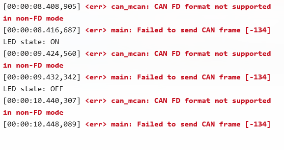
I am using VS Code to develop on the nRF52832, which is externally connected to a TCAN4550 CAN-FD chip. I successfully used the tcan4550evm.overlay to send and receive 8-byte CAN data normally. However, when I tried to send a CAN-FD format data packet, the operation failed. so,how to correctly send a CAN FD format data packet? I look forward to your reply.
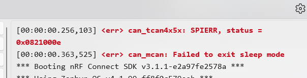
The printout shows the following error message.
My overlay configuration is as follows:
/ {
gpio_keys {
compatible = "gpio-keys";
pat9125_a_int: pat9125_a_int {
gpios = <&gpio0 11 GPIO_ACTIVE_LOW>;
label = "PAT9125_A_INT";
};
pat9125_b_int: pat9125_b_int {
gpios = <&gpio0 12 GPIO_ACTIVE_LOW>;
label = "PAT9125_B_INT";
};
};
aliases {
pat9125-a-int = &pat9125_a_int;
pat9125-b-int = &pat9125_b_int;
/* 将 can0 别名合并到这里 */
can0 = &tcan4x5x_tcan4550evm;
};
chosen {
zephyr,canbus = &tcan4x5x_tcan4550evm;
};
};
&i2c0 {
status = "okay";
pat9125_a: pat9125@73 {
compatible = "pixart,pat9125";
reg = <0x73>;
label = "PAT9125_A";
};
pat9125_b: pat9125@75 {
compatible = "pixart,pat9125";
reg = <0x75>;
label = "PAT9125_B";
};
};
&arduino_spi {
status = "okay";
cs-gpios = <&arduino_header 16 GPIO_ACTIVE_LOW>; /* D10 */
tcan4x5x_tcan4550evm: can@0 {
compatible = "ti,tcan4x5x";
reg = <0>;
spi-max-frequency = <2000000>;
clock-frequency = <40000000>;
device-state-gpios = <&arduino_header 12 GPIO_ACTIVE_HIGH>; /* D6 */
device-wake-gpios = <&arduino_header 13 GPIO_ACTIVE_HIGH>; /* D7 */
reset-gpios = <&arduino_header 14 GPIO_ACTIVE_HIGH>; /* D8 */
int-gpios = <&arduino_header 15 GPIO_ACTIVE_LOW>; /* D9 */
bosch,mram-cfg = <0x0 15 15 7 7 0 10 10>;
can-transceiver {
max-bitrate = <8000000>;
};
/* 在这里直接配置节点属性,而不是通过别名 */
bitrate = <500000>; /* 仲裁阶段波特率: 500 kbps */
bitrate-data = <500000>; /* 数据阶段波特率: 500 kbps */
sample-point = <875>; /* 仲裁阶段采样点: 87.5% */
sample-point-data = <875>; /* 数据阶段采样点: 87.5% */
status = "okay";
};
};
My prj configuration is as follows:
CONFIG_GPIO=y
CONFIG_I2C=y
CONFIG_CBPRINTF_FP_SUPPORT=y
# 确保日志已启用
CONFIG_LOG=y
# 设置默认日志级别(0=EMERG, 1=ALERT, 2=CRIT, 3=ERR, 4=WARNING, 5=INFO, 6=DEBUG, 7=VERBOSE)
CONFIG_LOG_DEFAULT_LEVEL=3
# 允许动态修改日志级别
CONFIG_LOG_MODE_IMMEDIATE=y
# 调试/监控
CONFIG_THREAD_MONITOR=y
CONFIG_THREAD_NAME=y
# 多线程支持
CONFIG_MULTITHREADING=y
CONFIG_NUM_COOP_PRIORITIES=16
CONFIG_NUM_PREEMPT_PRIORITIES=16
CONFIG_MAIN_STACK_SIZE=4096
# 线程分析器
CONFIG_THREAD_STACK_INFO=y
CONFIG_THREAD_ANALYZER=y
CONFIG_THREAD_ANALYZER_AUTO=y
CONFIG_THREAD_ANALYZER_USE_PRINTK=y
CONFIG_INIT_STACKS=y
# CAN总线配置
CONFIG_CAN=y
CONFIG_STATS=y
CONFIG_CAN_STATS=y
CONFIG_CAN_FD_MODE=y # 启用 Zephyr 的 CAN FD API 支持
# SPI配置
CONFIG_SPI=y # 启用 SPI 总线驱动(TCAN4550 的通信方式)
CONFIG_SPI_NRFX=y # nRF52硬件SPI驱动
CONFIG_SPI_NRFX_RAM_BUFFER_SIZE=128
CONFIG_PINCTRL=y # 启用引脚控制(通常是 SPI 和 GPIO 的依赖)
CONFIG_CAN_TCAN4X5X=y # 启用 TCAN4550 系列芯片的驱动程序
My main function is as follows:
int main(void)
{
int ret;
bool led_state = true;
if (!device_is_ready(led.port)) {
LOG_ERR("LED device %s is not ready", led.port->name);
return 0;
}
ret = gpio_pin_configure_dt(&led, GPIO_OUTPUT_ACTIVE);
if (ret < 0) {
LOG_ERR("Could not configure LED GPIO pin, error: %d", ret);
return 0;
}
/* 1. 检查CAN设备是否就绪 */
if (!device_is_ready(can_dev)) {
LOG_ERR("CAN device not ready!");
return 0;
}
/* 2. 启动CAN控制器 */
ret = can_start(can_dev);
if (ret != 0) {
LOG_ERR("Failed to start CAN controller [%d]", ret);
return 0;
}
/* 3. 设置一个过滤器,只接收ID为0x123的标准CAN帧 */
struct can_filter my_filter = {
.id = 0x123,
.mask = CAN_STD_ID_MASK, /* 只关心标准ID */
.flags = 0 /* 对于标准ID,此标志应为0。这里假设你想过滤标准ID的数据帧 */
};
/* 4. 将过滤器和回调函数附加到CAN设备 */
ret = can_add_rx_filter(can_dev, can_rx_callback, NULL, &my_filter);
if (ret < 0) {
LOG_ERR("Failed to add CAN RX filter [%d]", ret);
return 0;
}
LOG_INF("CAN application started");
while (1) {
//thread_analyzer_print(0);
ret = gpio_pin_toggle_dt(&led);
if (ret < 0) {
LOG_ERR("Could not toggle LED, error: %d", ret);
return 0;
}
led_state = !led_state;
printf("LED state: %s\n", led_state ? "ON" : "OFF");
/* 5. 构造并发送一条CAN消息 */
struct can_frame frame_to_send = {
.id = 0x456, /* 发送ID */
/* CAN FD 帧标志,BRS表示使用更快的比特率传输数据段 */
.flags = CAN_FRAME_FDF | CAN_FRAME_BRS,
.dlc = 12, /* 数据长度码, 9对应12字节. CAN FD DLC > 8 时有特殊含义 */
.data = {0x01, 0x02, 0x03, 0x04, 0x05, 0x06, 0x07, 0x08,0x01, 0x02, 0x03, 0x04}
};
frame_to_send.dlc = can_bytes_to_dlc(12); // 使用辅助函数将字节数转换为DLC值
ret = can_send(can_dev, &frame_to_send, K_SECONDS(1), NULL, NULL);
if (ret != 0) {
LOG_ERR("Failed to send CAN frame [%d]", ret);
}
/* 6. 等待并处理接收到的消息 */
struct can_frame received_frame;
if (k_msgq_get(&can_msgq, &received_frame, K_MSEC(500)) == 0) {
LOG_INF("CAN frame received! ID: 0x%03X, DLC: %d", received_frame.id, received_frame.dlc);
LOG_HEXDUMP_INF(received_frame.data, received_frame.dlc, "Data:");
}
k_msleep(SLEEP_TIME_MS);
}
return 0;
}