Unable to use LDO power on NRF52840

Hello,

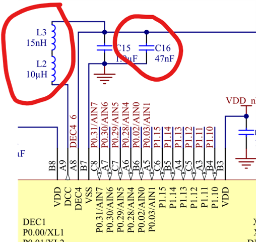
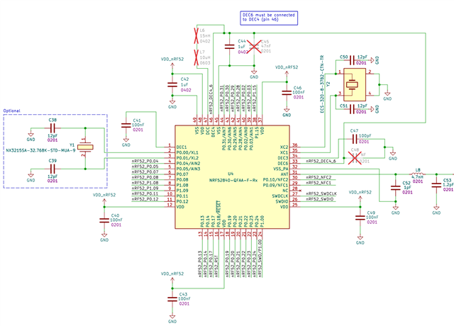
I want to use only LDO (not DC/DC) regulation on my nRF52840 design. The documentation states that LDO is the default for both REG0 and REG1, and that DC/DC should only be enabled if the external LC filter is present. Based on this, I removed the LC filter from my hardware.

However, after removing the LC filter, behavior is unstable:

  • Sometimes the chip fails to program,
  • Sometimes it programs but does not run.

My questions:

  1. What is the correct way to ensure the nRF52840 always uses LDO mode for both REG0 and REG1, both in hardware and firmware?
  2. Are there specific devicetree or Kconfig settings required to guarantee LDO mode and prevent the firmware from enabling DC/DC by default?
  3. Is it safe to remove the LC filter if LDO mode is always used, or could there be other issues?
  4. What could cause programming or boot failures after removing the LC filter, even though LDO should be the default?

What I have tried:

  • In the devicetree, I set:
    &reg1 { regulator-initial-mode = <NRF5X_REG_MODE_LDO>; };

Is there a checklist or best practice to ensure the nRF52840 is always in LDO mode and safe to run without the DC/DC LC filter? What else should I check if I still see programming or boot issues?

Thank you!

  • Hi

    The Devicetree setting you set iis indeed the default setting, so making sure this is what is set should be sufficient if you're on NCS v2.8.0 or later. Please confirm which SDK version you're working on.

    The behavior you describe doesn't sound typical for when DCDC is enabled but the components are missing, as that usually locks the device up entirely, so I don't think that is it here. Can you say specifically which components you removed from your board? Did you just remove the two inductors or any additional components? There are three extra components added when DCDC is used, so those three should be removed with everything else being untouched: 

    Best regards,

    Simon

  • Hi Simonr,

    Thank you for your reply. I only removed L2 and L3, not the C16. After removing C16, I can flash firmware to the chip without error. But it seems the firmware is not running. I have attached my schematic here, could you please review it?


    About firmware, I'm using NCS v2.9.1, and using default setting now. When run debugging, it found out that under POWER, register DCDCEN has value 1 which is Enabled, and DCDCEN0 has value 0 which is Disabled. Is it the expected value?

  • Hi

    The schematics look good. Both DCDCEN registers should be set to 0 (disabled). This should be disabled by default AFAIK, but you can set &reg0 { regulator-initial-mode = <NRF5X_REG_MODE_LDO>; }; to make sure as well. Note that if it has been run with DCDCEN0 enabled at all without the required components, it not certain that you'll be able to reflash the device.

    Best regards,

    Simon

  • Hi, thank you for your suggestion, I created a blank application and was able to successfully set both reg to disabled. It also worked on our PCB board.

    But the firmware of the project I'm working on still failed even with the same setting as the blank one I created. Is there any chance that some component on zephyr can automatically override those config and make the chip use DCDC power instead of LDO?. I'm using UART, BLE, NFC on the project.

  • Hi Simonr,

    It turns out that the MCU boot enable DCDC by default and try disabling it on the app takes no effect. I added this to also the mcuboot.overlay, not just the app overlay, and it worked:
    &reg1 { regulator-initial-mode = <NRF5X_REG_MODE_LDO>; };

Related