Controlling LED through pwm using nrfx or other offloading way for nrf54l15

Hi,

I am trying to do pwm a rgb led using nrf54l15dk and custom board using nrf54l15 on port1 with pin connections on (p1.10, p1.8 and p1.13 for custom) or on (p1.11, p1.12 and p1.10 for nrf54l15dk).

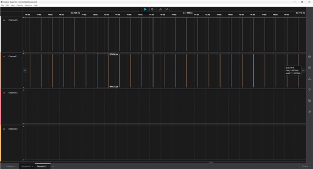
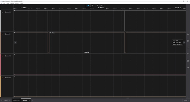
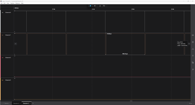
So, on nrf54l15dk I am able to do pwm using pwm_set_dt command, but it consumes CPU cycles so, I want to move that to nrf_pwm_sequence_t command which works fine in nrf52840. When I tried nrf_pwm_sequence_t it did not modulate pulse which it should do. 

I tried doing using both common and individual load, still no luck.

#define TOP_VAL_FADE 250
#define STEP_COUNT_FADE 25

static nrfx_pwm_t m_pwm20 = NRFX_PWM_INSTANCE(20);
static nrfx_pwm_t m_pwm21 = NRFX_PWM_INSTANCE(21);

static nrf_pwm_values_common_t fade_in_out_values[2 * STEP_COUNT_FADE];
static nrf_pwm_sequence_t led_on_seq;
static nrf_pwm_sequence_t led_off_seq;
static nrf_pwm_values_common_t stay_off_values[2] = {0};

void set_fade_values_common(void)
{
    for (uint32_t i = 0; i < STEP_COUNT_FADE; i++)
    {
        uint16_t value = (TOP_VAL_FADE * (i + 1)) / STEP_COUNT_FADE;
        fade_in_out_values[i] = value;
        fade_in_out_values[STEP_COUNT_FADE + i] = TOP_VAL_FADE - value;
        LOG_INF("value of fade %d: %d", i, value);
    }
}

void start_pwm_pulse(void)
{    
    // Configure fade in/out sequence
    led_on_seq.values.p_common = fade_in_out_values;
    led_on_seq.length = NRF_PWM_VALUES_LENGTH(fade_in_out_values);
    led_on_seq.repeats = 160; // All we have to do is update the repeats! Less repeats = faster fade in/out
    led_on_seq.end_delay = 0;
    
    // Configure off sequence
    led_off_seq.values.p_common = stay_off_values;
    led_off_seq.length = NRF_PWM_VALUES_LENGTH(stay_off_values);
    led_off_seq.repeats = 30;
    led_off_seq.end_delay = 0;
    
    // Start playback
    nrfx_pwm_complex_playback(&m_pwm20, &led_on_seq, &led_off_seq, 1, NRFX_PWM_FLAG_LOOP);
    nrfx_pwm_complex_playback(&m_pwm21, &led_on_seq, &led_off_seq, 1, NRFX_PWM_FLAG_LOOP);
    
    LOG_INF("PWM pulse started");
}

static int ktd2026_init(const struct device *dev) {
    LOG_DBG("LED Softblink init");

    nrfx_pwm_config_t config20 = {
        // .output_pins = { RED_PIN, GREEN_PIN, 0xFF, 0xFF }, // 0xFF = NRFX_PWM_PIN_NOT_USED
        .output_pins = { RED_PIN, 0xFF, 0xFF, 0xFF }, // 0xFF = NRFX_PWM_PIN_NOT_USED
        .irq_priority = 7,
        .base_clock   = NRF_PWM_CLK_1MHz,
        .count_mode   = NRF_PWM_MODE_UP,
        .top_value    = TOP_VAL_FADE,
        .load_mode    = NRF_PWM_LOAD_COMMON,
        .step_mode    = NRF_PWM_STEP_AUTO
    };
    nrfx_pwm_config_t config21 = {
        .output_pins = { GREEN_PIN, 0xFF, 0xFF, 0xFF }, // 0xFF = NRFX_PWM_PIN_NOT_USED
        .irq_priority = 7,
        .base_clock   = NRF_PWM_CLK_1MHz,
        .count_mode   = NRF_PWM_MODE_UP,
        .top_value    = TOP_VAL_FADE,
        .load_mode    = NRF_PWM_LOAD_COMMON,
        .step_mode    = NRF_PWM_STEP_AUTO
    };

    if (!nrfx_pwm_init_check(&m_pwm20)) {
        nrfx_err_t err = nrfx_pwm_init(&m_pwm20, &config20, NULL, NULL);
        if (err != NRFX_SUCCESS) {
            LOG_ERR("PWM20 init failed: %d", err);
            return -EIO;
        }
    } else {
        LOG_INF("PWM20 already initialized");
    }

    if (!nrfx_pwm_init_check(&m_pwm21)) {
        nrfx_err_t err = nrfx_pwm_init(&m_pwm21, &config21, NULL, NULL);
        if (err != NRFX_SUCCESS) {
            LOG_ERR("PWM21 init failed: %d", err);
            return -EIO;
        }
    } else {
        LOG_INF("PWM21 already initialized");
    }

    set_fade_values_common();

    return 0;
}


and with individual
#define TOP_VAL_FADE 250
#define STEP_COUNT_FADE 25

static nrfx_pwm_t m_pwm20 = NRFX_PWM_INSTANCE(20);
static nrfx_pwm_t m_pwm21 = NRFX_PWM_INSTANCE(21);

static nrf_pwm_values_individual_t fade_in_out_values[2 * STEP_COUNT_FADE];
static nrf_pwm_sequence_t led_on_seq;
static nrf_pwm_sequence_t led_off_seq;
static nrf_pwm_values_individual_t stay_off_values[2] = {0};

void set_fade_values_individual(void)
{
    for (uint32_t i = 0; i < STEP_COUNT_FADE; i++)
    {
        uint16_t value = (TOP_VAL_FADE * (i + 1)) / STEP_COUNT_FADE;
        
        // Fade in
        fade_in_out_values[i].channel_0 = value; // Red
        fade_in_out_values[i].channel_1 = value;     // Green
        fade_in_out_values[i].channel_2 = 0;     // Blue
        fade_in_out_values[i].channel_3 = 0;
        
        // Fade out
        fade_in_out_values[STEP_COUNT_FADE + i].channel_0 = TOP_VAL_FADE - value;
        fade_in_out_values[STEP_COUNT_FADE + i].channel_1 = TOP_VAL_FADE - value;
        fade_in_out_values[STEP_COUNT_FADE + i].channel_2 = 0;
        fade_in_out_values[STEP_COUNT_FADE + i].channel_3 = 0;
        LOG_INF("value of fade %d: %d", i, value);
    }
}

void start_pwm_pulse(uint32_t ramp_time_ms)
{    
    // Configure fade in/out sequence
    led_on_seq.values.p_individual = fade_in_out_values;
    led_on_seq.length = NRF_PWM_VALUES_LENGTH(fade_in_out_values);
    led_on_seq.repeats = 160; // All we have to do is update the repeats! Less repeats = faster fade in/out
    led_on_seq.end_delay = 0;
    
    // Configure off sequence
    led_off_seq.values.p_individual = stay_off_values;
    led_off_seq.length = NRF_PWM_VALUES_LENGTH(stay_off_values);
    led_off_seq.repeats = 30;
    led_off_seq.end_delay = 0;
    
    // Start playback
    nrfx_pwm_complex_playback(&m_pwm20, &led_on_seq, &led_off_seq, 1, NRFX_PWM_FLAG_LOOP);
    nrfx_pwm_complex_playback(&m_pwm21, &led_on_seq, &led_off_seq, 1, NRFX_PWM_FLAG_LOOP);
    
    LOG_INF("PWM pulse started");
}

static int ktd2026_init(const struct device *dev) {
    LOG_DBG("LED Softblink init");

    nrfx_pwm_config_t config20 = {
        // .output_pins = { RED_PIN, GREEN_PIN, 0xFF, 0xFF }, // 0xFF = NRFX_PWM_PIN_NOT_USED
        .output_pins = { RED_PIN, 0xFF, 0xFF, 0xFF }, // 0xFF = NRFX_PWM_PIN_NOT_USED
        .irq_priority = 7,
        .base_clock   = NRF_PWM_CLK_1MHz,
        .count_mode   = NRF_PWM_MODE_UP,
        .top_value    = RED_PWM_PERIOD_NS,
        .load_mode    = NRF_PWM_LOAD_INDIVIDUAL,
        .step_mode    = NRF_PWM_STEP_AUTO
    };
    nrfx_pwm_config_t config21 = {
        .output_pins = { GREEN_PIN, 0xFF, 0xFF, 0xFF }, // 0xFF = NRFX_PWM_PIN_NOT_USED
        .irq_priority = 7,
        .base_clock   = NRF_PWM_CLK_1MHz,
        .count_mode   = NRF_PWM_MODE_UP,
        .top_value    = RED_PWM_PERIOD_NS,
        .load_mode    = NRF_PWM_LOAD_INDIVIDUAL,
        .step_mode    = NRF_PWM_STEP_AUTO
    };

    if (!nrfx_pwm_init_check(&m_pwm20)) {
        nrfx_err_t err = nrfx_pwm_init(&m_pwm20, &config20, NULL, NULL);
        if (err != NRFX_SUCCESS) {
            LOG_ERR("PWM20 init failed: %d", err);
            return -EIO;
        }
    } else {
        LOG_INF("PWM20 already initialized");
    }

    if (!nrfx_pwm_init_check(&m_pwm21)) {
        nrfx_err_t err = nrfx_pwm_init(&m_pwm21, &config21, NULL, NULL);
        if (err != NRFX_SUCCESS) {
            LOG_ERR("PWM21 init failed: %d", err);
            return -EIO;
        }
    } else {
        LOG_INF("PWM21 already initialized");
    }

    set_fade_values_individual();

    return 0;
}


Parents
  • Hi!

    on nrf54l15dk I am able to do pwm using pwm_set_dt command, but it consumes CPU cycles so,

    Could you elaborate on this? You need to call pwm_set_dt() very often to get the desired signal?

  • Yes, when I use pwm_set_dt with different duty cycle, I am able to see different led intensity and when placed inside a while or for loop with changing duty cycle, I am able to get a pulse led for a desired time and speed. 

    Like I am able to set led pulse of 3 sec running for 10 sec or desired time or the loop is true.

    But, using this method for pwm, CPU needs to update and send that command to pin which is power consuming. So, I found a way that in nrf52840, but using nrfx_sequence, I can reduce power consumption and CPU can work on other tasks.

    So, while porting to nrf54l15, I am unable to load off that task to nrfx_sequence. So, I am trying to find a way to work with nrfx_sequence in nrf54l15.

  • Hi!

    Maybe you can do it like this:

    /*
     * Copyright (c) 2012-2014 Wind River Systems, Inc.
     *
     * SPDX-License-Identifier: Apache-2.0
     */
    
    #include <stdio.h>
    #include <zephyr/kernel.h>
    #include <zephyr/irq.h>
    #include <nrfx_pwm.h>
    #include <hal/nrf_gpio.h>
    #include <zephyr/logging/log.h>
    
    LOG_MODULE_REGISTER(pwm_example, LOG_LEVEL_INF);
    
    /* PWM output pins on PORT 1 for RGB LED */
    #define RED_PIN   NRF_GPIO_PIN_MAP(1, 11)  /* P1.11 */
    #define GREEN_PIN NRF_GPIO_PIN_MAP(1, 12)  /* P1.12 */
    #define BLUE_PIN  NRF_GPIO_PIN_MAP(1, 10)  /* P1.10 */
    
    /* PWM fade parameters */
    #define TOP_VAL_FADE 250
    #define STEP_COUNT_FADE 25
    
    /* PWM instances */
    static nrfx_pwm_t m_pwm20 = NRFX_PWM_INSTANCE(20);
    
    /* Fade in/out sequence values */
    static nrf_pwm_values_common_t fade_in_out_values[2 * STEP_COUNT_FADE];
    static nrf_pwm_sequence_t led_on_seq;
    static nrf_pwm_sequence_t led_off_seq;
    static nrf_pwm_values_common_t stay_off_values[2] = {0, 0};
    
    /**
     * @brief Set up fade in/out values.
     * 
     * Creates a smooth fade pattern by calculating incrementing values
     * for fade-in and decrementing values for fade-out.
     */
    void set_fade_values_common(void)
    {
        for (uint32_t i = 0; i < STEP_COUNT_FADE; i++)
        {
            uint16_t value = (TOP_VAL_FADE * (i + 1)) / STEP_COUNT_FADE;
            fade_in_out_values[i] = value;
            fade_in_out_values[STEP_COUNT_FADE + i] = TOP_VAL_FADE - value;
            LOG_INF("Fade value %d: %d", i, value);
        }
    }
    
    /**
     * @brief Start PWM pulse with fade in/out effect.
     * 
     * Configures two sequences: one for fading in/out and one for staying off.
     * Uses complex playback to alternate between the sequences in a loop.
     */
    void start_pwm_pulse(void)
    {    
        // Configure fade in/out sequence
        led_on_seq.values.p_common = fade_in_out_values;
        led_on_seq.length = NRF_PWM_VALUES_LENGTH(fade_in_out_values);
        led_on_seq.repeats = 160; // Less repeats = faster fade in/out
        led_on_seq.end_delay = 0;
        
        // Configure off sequence
        led_off_seq.values.p_common = stay_off_values;
        led_off_seq.length = NRF_PWM_VALUES_LENGTH(stay_off_values);
        led_off_seq.repeats = 30;
        led_off_seq.end_delay = 0;
        
        // Start complex playback with looping
        nrfx_err_t err = nrfx_pwm_complex_playback(&m_pwm20, &led_on_seq, &led_off_seq, 1, NRFX_PWM_FLAG_LOOP);
        if (err != NRFX_SUCCESS) {
            LOG_ERR("PWM complex playback failed: %d", err);
        } else {
            LOG_INF("PWM pulse started with fade in/out effect");
        }
    }
    
    /**
     * @brief Initialize PWM20 for fade effect.
     * 
     * @return 0 on success, negative error code on failure.
     */
    static int pwm_fade_init(void)
    {
        LOG_INF("PWM Fade example init - RGB LED");
    
        nrfx_pwm_config_t config20 = {
            .output_pins = { RED_PIN, GREEN_PIN, BLUE_PIN, NRF_PWM_PIN_NOT_CONNECTED },
            .irq_priority = 7,
            .base_clock   = NRF_PWM_CLK_1MHz,
            .count_mode   = NRF_PWM_MODE_UP,
            .top_value    = TOP_VAL_FADE,
            .load_mode    = NRF_PWM_LOAD_COMMON,
            .step_mode    = NRF_PWM_STEP_AUTO
        };
    
        if (!nrfx_pwm_init_check(&m_pwm20)) {
            nrfx_err_t err = nrfx_pwm_init(&m_pwm20, &config20, NULL, NULL);
            if (err != NRFX_SUCCESS) {
                LOG_ERR("PWM20 init failed: %d", err);
                return -EIO;
            }
            LOG_INF("PWM20 initialized successfully");
        } else {
            LOG_INF("PWM20 already initialized");
        }
    
        set_fade_values_common();
    
        return 0;
    }
    
    
    int main(void)
    {
    	int ret;
    	
    	printf("PWM Fade Example for nRF54L15! %s\n", CONFIG_BOARD_TARGET);
    	printf("Using PWM20 instance with fade in/out effect on PORT 1 pins\n");
    
    	/* Initialize PWM with fade configuration */
    	ret = pwm_fade_init();
    	if (ret != 0) {
    		LOG_ERR("PWM fade initialization failed: %d", ret);
    		return ret;
    	}
    	
    	/* Start PWM pulse with fade effect */
    	start_pwm_pulse();
    	
    	printf("PWM fade effect started on RGB LED:\n");
    	printf("  Red   (P1.11): Breathing LED effect\n");
    	printf("  Green (P1.12): Breathing LED effect\n");
    	printf("  Blue  (P1.10): Breathing LED effect\n");
    	printf("Running indefinitely...\n");
    
    
    	while (1) {
    		k_sleep(K_SECONDS(100));
    	}
    
    	return 0;
    }
    

    prj.conf

    # Enable nrfx PWM20 driver instance
    CONFIG_NRFX_PWM20=y
    
    # Enable logging
    CONFIG_LOG=y

    nrf54l15dk_nrf54l15_cpuapp.overlay

    /*
     * Copyright (c) 2025 Nordic Semiconductor ASA
     *
     * SPDX-License-Identifier: Apache-2.0
     */
    
    /* Configure PWM20 to use pins on PORT 1 for RGB LED */
    
    &pinctrl {
    	pwm20_default: pwm20_default {
    		group1 {
    			psels = <NRF_PSEL(PWM_OUT0, 1, 11)>,  /* Red */
    				<NRF_PSEL(PWM_OUT1, 1, 12)>,  /* Green */
    				<NRF_PSEL(PWM_OUT2, 1, 10)>;  /* Blue */
    		};
    	};
    
    	pwm20_sleep: pwm20_sleep {
    		group1 {
    			psels = <NRF_PSEL(PWM_OUT0, 1, 11)>,  /* Red */
    				<NRF_PSEL(PWM_OUT1, 1, 12)>,  /* Green */
    				<NRF_PSEL(PWM_OUT2, 1, 10)>;  /* Blue */
    			low-power-enable;
    		};
    	};
    };
    
    &pwm20 {
    	status = "okay";
    	pinctrl-0 = <&pwm20_default>;
    	pinctrl-1 = <&pwm20_sleep>;
    	pinctrl-names = "default", "sleep";
    };
    

Reply
  • Hi!

    Maybe you can do it like this:

    /*
     * Copyright (c) 2012-2014 Wind River Systems, Inc.
     *
     * SPDX-License-Identifier: Apache-2.0
     */
    
    #include <stdio.h>
    #include <zephyr/kernel.h>
    #include <zephyr/irq.h>
    #include <nrfx_pwm.h>
    #include <hal/nrf_gpio.h>
    #include <zephyr/logging/log.h>
    
    LOG_MODULE_REGISTER(pwm_example, LOG_LEVEL_INF);
    
    /* PWM output pins on PORT 1 for RGB LED */
    #define RED_PIN   NRF_GPIO_PIN_MAP(1, 11)  /* P1.11 */
    #define GREEN_PIN NRF_GPIO_PIN_MAP(1, 12)  /* P1.12 */
    #define BLUE_PIN  NRF_GPIO_PIN_MAP(1, 10)  /* P1.10 */
    
    /* PWM fade parameters */
    #define TOP_VAL_FADE 250
    #define STEP_COUNT_FADE 25
    
    /* PWM instances */
    static nrfx_pwm_t m_pwm20 = NRFX_PWM_INSTANCE(20);
    
    /* Fade in/out sequence values */
    static nrf_pwm_values_common_t fade_in_out_values[2 * STEP_COUNT_FADE];
    static nrf_pwm_sequence_t led_on_seq;
    static nrf_pwm_sequence_t led_off_seq;
    static nrf_pwm_values_common_t stay_off_values[2] = {0, 0};
    
    /**
     * @brief Set up fade in/out values.
     * 
     * Creates a smooth fade pattern by calculating incrementing values
     * for fade-in and decrementing values for fade-out.
     */
    void set_fade_values_common(void)
    {
        for (uint32_t i = 0; i < STEP_COUNT_FADE; i++)
        {
            uint16_t value = (TOP_VAL_FADE * (i + 1)) / STEP_COUNT_FADE;
            fade_in_out_values[i] = value;
            fade_in_out_values[STEP_COUNT_FADE + i] = TOP_VAL_FADE - value;
            LOG_INF("Fade value %d: %d", i, value);
        }
    }
    
    /**
     * @brief Start PWM pulse with fade in/out effect.
     * 
     * Configures two sequences: one for fading in/out and one for staying off.
     * Uses complex playback to alternate between the sequences in a loop.
     */
    void start_pwm_pulse(void)
    {    
        // Configure fade in/out sequence
        led_on_seq.values.p_common = fade_in_out_values;
        led_on_seq.length = NRF_PWM_VALUES_LENGTH(fade_in_out_values);
        led_on_seq.repeats = 160; // Less repeats = faster fade in/out
        led_on_seq.end_delay = 0;
        
        // Configure off sequence
        led_off_seq.values.p_common = stay_off_values;
        led_off_seq.length = NRF_PWM_VALUES_LENGTH(stay_off_values);
        led_off_seq.repeats = 30;
        led_off_seq.end_delay = 0;
        
        // Start complex playback with looping
        nrfx_err_t err = nrfx_pwm_complex_playback(&m_pwm20, &led_on_seq, &led_off_seq, 1, NRFX_PWM_FLAG_LOOP);
        if (err != NRFX_SUCCESS) {
            LOG_ERR("PWM complex playback failed: %d", err);
        } else {
            LOG_INF("PWM pulse started with fade in/out effect");
        }
    }
    
    /**
     * @brief Initialize PWM20 for fade effect.
     * 
     * @return 0 on success, negative error code on failure.
     */
    static int pwm_fade_init(void)
    {
        LOG_INF("PWM Fade example init - RGB LED");
    
        nrfx_pwm_config_t config20 = {
            .output_pins = { RED_PIN, GREEN_PIN, BLUE_PIN, NRF_PWM_PIN_NOT_CONNECTED },
            .irq_priority = 7,
            .base_clock   = NRF_PWM_CLK_1MHz,
            .count_mode   = NRF_PWM_MODE_UP,
            .top_value    = TOP_VAL_FADE,
            .load_mode    = NRF_PWM_LOAD_COMMON,
            .step_mode    = NRF_PWM_STEP_AUTO
        };
    
        if (!nrfx_pwm_init_check(&m_pwm20)) {
            nrfx_err_t err = nrfx_pwm_init(&m_pwm20, &config20, NULL, NULL);
            if (err != NRFX_SUCCESS) {
                LOG_ERR("PWM20 init failed: %d", err);
                return -EIO;
            }
            LOG_INF("PWM20 initialized successfully");
        } else {
            LOG_INF("PWM20 already initialized");
        }
    
        set_fade_values_common();
    
        return 0;
    }
    
    
    int main(void)
    {
    	int ret;
    	
    	printf("PWM Fade Example for nRF54L15! %s\n", CONFIG_BOARD_TARGET);
    	printf("Using PWM20 instance with fade in/out effect on PORT 1 pins\n");
    
    	/* Initialize PWM with fade configuration */
    	ret = pwm_fade_init();
    	if (ret != 0) {
    		LOG_ERR("PWM fade initialization failed: %d", ret);
    		return ret;
    	}
    	
    	/* Start PWM pulse with fade effect */
    	start_pwm_pulse();
    	
    	printf("PWM fade effect started on RGB LED:\n");
    	printf("  Red   (P1.11): Breathing LED effect\n");
    	printf("  Green (P1.12): Breathing LED effect\n");
    	printf("  Blue  (P1.10): Breathing LED effect\n");
    	printf("Running indefinitely...\n");
    
    
    	while (1) {
    		k_sleep(K_SECONDS(100));
    	}
    
    	return 0;
    }
    

    prj.conf

    # Enable nrfx PWM20 driver instance
    CONFIG_NRFX_PWM20=y
    
    # Enable logging
    CONFIG_LOG=y

    nrf54l15dk_nrf54l15_cpuapp.overlay

    /*
     * Copyright (c) 2025 Nordic Semiconductor ASA
     *
     * SPDX-License-Identifier: Apache-2.0
     */
    
    /* Configure PWM20 to use pins on PORT 1 for RGB LED */
    
    &pinctrl {
    	pwm20_default: pwm20_default {
    		group1 {
    			psels = <NRF_PSEL(PWM_OUT0, 1, 11)>,  /* Red */
    				<NRF_PSEL(PWM_OUT1, 1, 12)>,  /* Green */
    				<NRF_PSEL(PWM_OUT2, 1, 10)>;  /* Blue */
    		};
    	};
    
    	pwm20_sleep: pwm20_sleep {
    		group1 {
    			psels = <NRF_PSEL(PWM_OUT0, 1, 11)>,  /* Red */
    				<NRF_PSEL(PWM_OUT1, 1, 12)>,  /* Green */
    				<NRF_PSEL(PWM_OUT2, 1, 10)>;  /* Blue */
    			low-power-enable;
    		};
    	};
    };
    
    &pwm20 {
    	status = "okay";
    	pinctrl-0 = <&pwm20_default>;
    	pinctrl-1 = <&pwm20_sleep>;
    	pinctrl-names = "default", "sleep";
    };
    

Children
  • Hi Sigurd,

    I tried the provided code with provided configurations and got the same result as I had earlier.

    Serial output

    PWM Fade Example for nRF54L15! nrf54l15dk/nrf54l15/cpuapp
    Using PWM20 instance with fade in/out effect on PORT 1 pins
    PWM fade effect started on RGB LED:
      Red   (P1.11): Breathing LED effect
      Green (P1.12): Breathing LED effect
      Blue  (P1.10): Breathing LED effect
    Running indefinitely...
    *** Booting nRF Connect SDK v3.0.1-9eb5615da66b ***
    *** Using Zephyr OS v4.0.99-77f865b8f8d0 ***
    [00:00:00.012,387] <inf> tests_pwm_example: PWM Fade example init - RGB LED
    [00:00:00.012,393] <inf> tests_pwm_example: PWM20 already initialized
    [00:00:00.012,398] <inf> tests_pwm_example: Fade value 0: 10
    [00:00:00.012,402] <inf> tests_pwm_example: Fade value 1: 20
    [00:00:00.012,406] <inf> tests_pwm_example: Fade value 2: 30
    [00:00:00.012,410] <inf> tests_pwm_example: Fade value 3: 40
    [00:00:00.012,414] <inf> tests_pwm_example: Fade value 4: 50
    [00:00:00.012,418] <inf> tests_pwm_example: Fade value 5: 60
    [00:00:00.012,422] <inf> tests_pwm_example: Fade value 6: 70
    [00:00:00.012,426] <inf> tests_pwm_example: Fade value 7: 80
    [00:00:00.012,431] <inf> tests_pwm_example: Fade value 8: 90
    [00:00:00.012,435] <inf> tests_pwm_example: Fade value 9: 100
    [00:00:00.012,439] <inf> tests_pwm_example: Fade value 10: 110
    [00:00:00.012,443] <inf> tests_pwm_example: Fade value 11: 120
    [00:00:00.012,447] <inf> tests_pwm_example: Fade value 12: 130
    [00:00:00.012,451] <inf> tests_pwm_example: Fade value 13: 140
    [00:00:00.012,455] <inf> tests_pwm_example: Fade value 14: 150
    [00:00:00.012,459] <inf> tests_pwm_example: Fade value 15: 160
    [00:00:00.012,463] <inf> tests_pwm_example: Fade value 16: 170
    [00:00:00.012,467] <inf> tests_pwm_example: Fade value 17: 180
    [00:00:00.012,472] <inf> tests_pwm_example: Fade value 18: 190
    [00:00:00.012,476] <inf> tests_pwm_example: Fade value 19: 200
    [00:00:00.012,480] <inf> tests_pwm_example: Fade value 20: 210
    [00:00:00.012,484] <inf> tests_pwm_example: Fade value 21: 220
    [00:00:00.012,488] <inf> tests_pwm_example: Fade value 22: 230
    [00:00:00.012,492] <inf> tests_pwm_example: Fade value 23: 240
    [00:00:00.012,496] <inf> tests_pwm_example: Fade value 24: 250
    [00:00:00.012,505] <err> tests_pwm_example: PWM complex playback failed: 0


    I searched for the playback failed: 0 reason and found this

    "PWM complex playback failed: 0, indicates that the function nrfx_pwm_complex_playback is returning 0. The return value of nrfx_pwm_complex_playback is not an error code, but rather the address of the task to be triggered if the NRFX_PWM_FLAG_START_VIA_TASK flag is used. If this flag is not used, the function returns 0, which is expected and does not indicate an error."


    and here is the logic analyzer output for pin 1.11 and 1.12


    as you can see the pwm is almost same for all signals, and that's the reason I am unable to see any pulse or blinking effect.

  • Hi Sigurd,

    Here is my dts/binding

    description: Custom binding for an RGB LED controlled by three PWM channels
    
    compatible: "led,nrf54_rgb_pwm"
    
    properties:
      pwms:
        type: phandle-array
        required: true
        description: |
          List of PWM specifiers for the RGB channels.
          The order should be: red, green, blue.
      pwm-names:
        type: string-array
        required: true
        description: |
          List the names of the pwm lines for RGB.


    and my .overlay
    /{
            leds: led {
            compatible = "led,nrf54_rgb_pwm";
            status = "okay";
            pwms = <&pwm20 0 PWM_MSEC(1) PWM_POLARITY_NORMAL>,
                   <&pwm20 1 PWM_MSEC(1) PWM_POLARITY_NORMAL>,
                   <&pwm20 2 PWM_MSEC(1) PWM_POLARITY_NORMAL>;
            pwm-names = "red_pwms", "green_pwms", "blue_pwms";
        };
    
        aliases {
            rgb-led     = &leds;
        };
        
        pwm20_default: pwm20_default {
            group1 {
                psels = <NRF_PSEL(PWM_OUT0, 1, 11)>,
                        <NRF_PSEL(PWM_OUT1, 1, 12)>,
                        <NRF_PSEL(PWM_OUT2, 1, 13)>;
            };
        };
        pwm20_sleep: pwm20_sleep {
            group1 {
                psels = <NRF_PSEL(PWM_OUT0, 1, 11)>,
                        <NRF_PSEL(PWM_OUT1, 1, 12)>,
                        <NRF_PSEL(PWM_OUT2, 1, 13)>;
                low-power-enable;
            };
        };
    };
    
    &pwm20 {
    	status = "okay";
    	pinctrl-0 = <&pwm20_default>;
    	pinctrl-1 = <&pwm20_sleep>;
    	pinctrl-names = "default","sleep";
    };


    I am still unable to pulse the led using nrf_pwm_sequence_t. Can you help me out?

  • Hi!

    Try this main.c 

    /*
     * Copyright (c) 2012-2014 Wind River Systems, Inc.
     *
     * SPDX-License-Identifier: Apache-2.0
     */
    
    #include <stdio.h>
    #include <zephyr/kernel.h>
    #include <zephyr/sys/util.h>
    #include <zephyr/irq.h>
    #include <nrfx_pwm.h>
    #include <hal/nrf_gpio.h>
    #include <zephyr/logging/log.h>
    
    LOG_MODULE_REGISTER(pwm_example, LOG_LEVEL_INF);
    
    /* PWM output pins on PORT 1 for RGB LED */
    #define RED_PIN   NRF_GPIO_PIN_MAP(1, 11)  /* P1.11 */
    #define GREEN_PIN NRF_GPIO_PIN_MAP(1, 12)  /* P1.12 */
    #define BLUE_PIN  NRF_GPIO_PIN_MAP(1, 13)  /* P1.13 */
    
    /* PWM fade parameters */
    #define TOP_VAL_FADE 250
    #define STEP_COUNT_FADE 25
    
    /* PWM instances */
    static nrfx_pwm_t m_pwm20 = NRFX_PWM_INSTANCE(20);
    
    /* Fade in/out sequence values */
    static nrf_pwm_values_individual_t fade_in_out_values[2 * STEP_COUNT_FADE];
    static nrf_pwm_sequence_t led_on_seq;
    static nrf_pwm_sequence_t led_off_seq;
    static nrf_pwm_values_individual_t stay_off_values[2];
    
    static uint16_t fade_value_for_step(uint32_t step_idx)
    {
        const uint32_t steps_per_phase = STEP_COUNT_FADE;
        const uint32_t total_steps = 2U * steps_per_phase;
        step_idx %= total_steps;
    
        uint32_t phase_pos = step_idx % steps_per_phase;
        uint16_t level = (TOP_VAL_FADE * (phase_pos + 1U)) / steps_per_phase;
    
        if (step_idx < steps_per_phase) {
            return level;
        }
    
        return TOP_VAL_FADE - level;
    }
    
    /**
     * @brief Set up fade in/out values.
     * 
     * Creates a smooth fade pattern by calculating incrementing values
     * for fade-in and decrementing values for fade-out.
     */
    void set_fade_values_common(void)
    {
        const uint32_t total_steps = ARRAY_SIZE(fade_in_out_values);
        const uint32_t green_phase = total_steps / 3U;
        const uint32_t blue_phase  = (2U * total_steps) / 3U;
    
        for (uint32_t i = 0; i < total_steps; i++)
        {
            fade_in_out_values[i].channel_0 = fade_value_for_step(i);
            fade_in_out_values[i].channel_1 = fade_value_for_step((i + green_phase) % total_steps);
            fade_in_out_values[i].channel_2 = fade_value_for_step((i + blue_phase) % total_steps);
            fade_in_out_values[i].channel_3 = 0;
    
            LOG_INF("Fade step %d -> R:%d G:%d B:%d",
                    i,
                    fade_in_out_values[i].channel_0,
                    fade_in_out_values[i].channel_1,
                    fade_in_out_values[i].channel_2);
        }
    
        for (size_t i = 0; i < ARRAY_SIZE(stay_off_values); i++) {
            stay_off_values[i].channel_0 = 0;
            stay_off_values[i].channel_1 = 0;
            stay_off_values[i].channel_2 = 0;
            stay_off_values[i].channel_3 = 0;
        }
    }
    
    /**
     * @brief Start PWM pulse with fade in/out effect.
     * 
     * Configures two sequences: one for fading in/out and one for staying off.
     * Uses complex playback to alternate between the sequences in a loop.
     */
    void start_pwm_pulse(void)
    {    
        // Configure fade in/out sequence
        led_on_seq.values.p_individual = fade_in_out_values;
        led_on_seq.length = NRF_PWM_VALUES_LENGTH(fade_in_out_values);
        led_on_seq.repeats = 160; // Less repeats = faster fade in/out
        led_on_seq.end_delay = 0;
        
        // Configure off sequence
        led_off_seq.values.p_individual = stay_off_values;
        led_off_seq.length = NRF_PWM_VALUES_LENGTH(stay_off_values);
        led_off_seq.repeats = 30;
        led_off_seq.end_delay = 0;
        
    
        uint32_t task_addr = nrfx_pwm_complex_playback(&m_pwm20, &led_on_seq, &led_off_seq, 1, NRFX_PWM_FLAG_LOOP);
        if (task_addr != 0) {
            LOG_INF("PWM playback prepared; trigger task at 0x%08x to start", task_addr);
        } else {
            LOG_INF("PWM pulse started with fade in/out effect");
        }
    }
    
    /**
     * @brief Initialize PWM20 for fade effect.
     * 
     * @return 0 on success, negative error code on failure.
     */
    static int pwm_fade_init(void)
    {
        LOG_INF("PWM Fade example init - RGB LED");
    
        nrfx_pwm_config_t config20 = {
            .output_pins = { RED_PIN, GREEN_PIN, BLUE_PIN, NRF_PWM_PIN_NOT_CONNECTED },
            .irq_priority = 7,
            .base_clock   = NRF_PWM_CLK_1MHz,
            .count_mode   = NRF_PWM_MODE_UP,
            .top_value    = TOP_VAL_FADE,
            .load_mode    = NRF_PWM_LOAD_INDIVIDUAL,
            .step_mode    = NRF_PWM_STEP_AUTO
        };
    
        if (!nrfx_pwm_init_check(&m_pwm20)) {
            nrfx_err_t err = nrfx_pwm_init(&m_pwm20, &config20, NULL, NULL);
            if (err != NRFX_SUCCESS) {
                LOG_ERR("PWM20 init failed: %d", err);
                return -EIO;
            }
            LOG_INF("PWM20 initialized successfully");
        } else {
            LOG_INF("PWM20 already initialized");
        }
    
        set_fade_values_common();
    
        return 0;
    }
    
    
    int main(void)
    {
    	int ret;
    	
    	LOG_INF("PWM Fade Example for nRF54L15! %s\n", CONFIG_BOARD_TARGET);
    	LOG_INF("Using PWM20 instance with fade in/out effect on PORT 1 pins\n");
    
    	/* Initialize PWM with fade configuration */
    	ret = pwm_fade_init();
    	if (ret != 0) {
    		LOG_ERR("PWM fade initialization failed: %d", ret);
    		return ret;
    	}
    	
    	/* Start PWM pulse with fade effect */
    	start_pwm_pulse();
    	
    	LOG_INF("PWM fade effect started on RGB LED:\n");
    	LOG_INF("  Red   (P1.11): Breathing LED effect\n");
    	LOG_INF("  Green (P1.12): Breathing LED effect\n");
    	LOG_INF("  Blue  (P1.13): Breathing LED effect\n");
    	LOG_INF("Running indefinitely...\n");
    
    
    	while (1) {
    		k_sleep(K_SECONDS(100));
    	}
    
    	return 0;
    }

  • Hi Sigurd,

    Thank you for the response.

    I figured out the problem, the code and everything is correct except for the overlay.

    The documents says that the nrfx and zephyr does not do together, so if using nrfx do not use pwm node.

    This is my updated .overlay and it works

    &pwm20 {
    	status = "disabled";
    	pinctrl-0 = <&pwm20_default>;
    	pinctrl-1 = <&pwm20_sleep>;
    	pinctrl-names = "default","sleep";
    };
    
    /{
    leds: led {
            compatible = "led,nrf54_rgb_pwm";
            status = "okay";
            pwms = <&pwm20 0 PWM_MSEC(1) PWM_POLARITY_NORMAL>,
                   <&pwm20 1 PWM_MSEC(1) PWM_POLARITY_NORMAL>,
                   <&pwm20 2 PWM_MSEC(1) PWM_POLARITY_NORMAL>;
            pwm-names = "red_pwms", "green_pwms", "blue_pwms";
        };
    };
    
    &pinctrl{
    pwm20_default: pwm20_default {
            group1 {
                psels = <NRF_PSEL(PWM_OUT0, 1, 10)>,
                        <NRF_PSEL(PWM_OUT1, 1, 8)>,
                        <NRF_PSEL(PWM_OUT2, 1, 13)>;
            };
        };
        pwm20_sleep: pwm20_sleep {
            group1 {
                psels = <NRF_PSEL(PWM_OUT0, 1, 10)>,
                        <NRF_PSEL(PWM_OUT1, 1, 8)>,
                        <NRF_PSEL(PWM_OUT2, 1, 13)>;
                low-power-enable;
            };
        };
    };


    and .conf
    CONFIG_PWM=n
    CONFIG_PWM_NRFX=n
    CONFIG_NRFX_PWM20=y

Related