How to properly configure RTT for a custom board

Hello everyone!

I'm trying to get a custom board based on the nRF54L10 working. I am currently connecting it to my computer via a J-Link Edu and would like to get some basic logging to work using RTT (the Edu doesn't support a virtual COM port).

I am using the following configuration:

  • MacOS Tahoe 26.1
  • nRF Connect SDK v3.1.1
  • nRF Connect Extension for VSCode
  • nRF54L10 based board
  • J-Link RTT Viewer

I have created a custom board using the extension, but didn't make any changes to it. My `prj.conf` is

CONFIG_GPIO=y

CONFIG_UART_CONSOLE=n
CONFIG_USE_SEGGER_RTT=y
CONFIG_RTT_CONSOLE=y

CONFIG_CONSOLE=y
CONFIG_LOG=y
CONFIG_LOG_DEFAULT_LEVEL=4

and I'm trying to run some basic sample code:

#include <zephyr/kernel.h>
#include <zephyr/sys/printk.h>

int main(void) {
    while (true) {
        printk("Hello, World!\n");
        k_msleep(1000);
    }

    return 0;
}

I seem to be able to successfully flash the microcontroller, as no errors occur during that process.

When I open the J-Link RTT Viewer, I get some log messages about the microcontroller and then `LOG: RTT Viewer connected.`, however no log messages arrive after that, even when resetting the microcontroller manually or from within the extension. I also cannot type into the send field as I get a warning saying 0 of 1 bytes were sent.

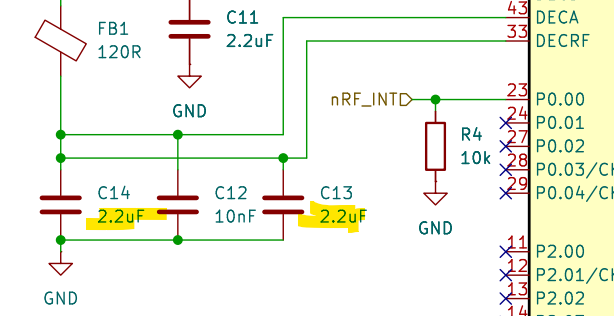
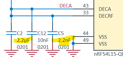
I have attached the schematic of the board and the project as a ZIP-Archive below.

Can anyone help me to configure RTT logging for my custom board?

Note: I'm not 100% confident in my soldering skills, however as flashing seems to work and with the J-Link being able to retrieve information from the microcontroller I'm assuming the MCU is at least online.

8420.project.zip8880.schematic.pdf

Parents
  • Hi,

    We can try making RTT work ofcourse, but I find that a blinky sample is even closer to what a hello world sample is trying to do when it comes to embedded - either that or checking if it manages to put a pin high. So just to check if it manages to flash the nRF, do you have an LED available?

    And btw, I would recommend starting off with a DK, that is an easier starting point.

    Regards,

    Elfving

  • Thanks for the response! I have tried a blinky sample already, but the pins just stay floating, so I wanted to check where it is failing by logging. Debugging doesn't work either, it breaks somewhere completely else than where the breakpoint is. I originally bought a different board with an nRF and only later realized that you need like a different bootloader for that and can't really program it with the connect SDK. I bought a proper DK now and will mess around with that a bit :D. Thanks for the help!

  • Gotya Slight smile No problem. A DK would be the recommended way to start, so going for that sounds like the best plan.

    Though I can't just let the original problem go without commenting on it here: Looks to me as if there might be small mistake here on DECRF, and the DEC pins are generally important for the RF performance. Though that alone wouldn't explain what you are seeing here ofcourse.

    My bet is that there is something that is missoldered somewhere. Did you manually solder the entire thing? Could you check the current draw of it, and the voltage on eg. this test point TP11?

    Regards,

    Elfving

  • Hi, sorry for the late reply! That with the capacitors is a funny mix up, I'll have to fix that lol.

    I reflow soldered the board using a hot plate. The MCU is currently drawing a little over 1mA at 3.3V, which does down to 0.3mA when holding the reset button.

  • That does sound like a lot. What are you running on it now? Do you just have the one board that you are seeing this on? Might be an idea to compare multiple, if you had them.

    Regards,

    Elfving

Reply Children
No Data
Related