nRF Connect SDK PWM on nRF52811 produces high power consumption with huge spikes not seen on nRF5 SDK PWM on the same MCU

Nordic support,

We are experiencing unexpectedly high and noisy power consumption when using PWM with nRF Connect SDK v2.9.2 on a nRF52811-based custom board, which is problematic because our use case for the nRF52811 is a board that is both ultra-low power and requires low noise on power rails while PWM is enabled. We'd like your help understanding what is causing this issue.

What is strange is that we do not see this same behavior when implementing identical code for this nRF52811-based board using the nRF5 SDK. We also do not see this behavior when using PWM with nRF Connect SDK on a nRF52840-based custom board. In other words, the problem seems to be specific to nRF5 Connect SDK running on the nRF52811.

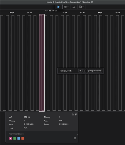
Our use case for PWM on this board is generating a 3.2 MHz clock to an external component. However, for the purposes of this testing, we are outputting PWM to a pad that is not connected to anything, to highlight the power consumption due to PWM vs whatever it is connected to.

Also, to simplify reproduction, all of our testing is performed using a modified version of zephyr/samples/basic/blinky, with main changed as follows:

int main(void)
{
    static const struct device *clk_dev = DEVICE_DT_GET(DT_NODELABEL(pwm_clock_gen));

    if (device_is_ready(clk_dev))
    {
        k_sleep(K_MSEC(100));

        clock_control_on(clk_dev, 0);
    }

    k_sleep(K_MSEC(1000));
}

So in our test, we sleep for 100ms, turn on the 3.2 MHz PWM output, and then sleep for 1000 seconds to contrast power consumption while our main thread is sleeping before and after PWM is enabled. Also, our nRF Connect SDK implementation relies on a custom, board-specific DTS file based on the nordic/nrf52811_qfaa.dtsi file (attached, named RC63_B25_V2_DEVKIT.dts.

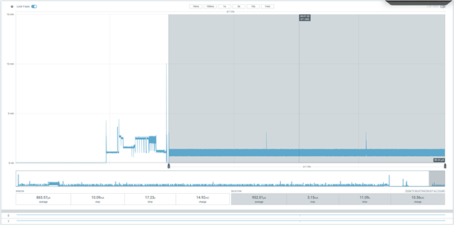
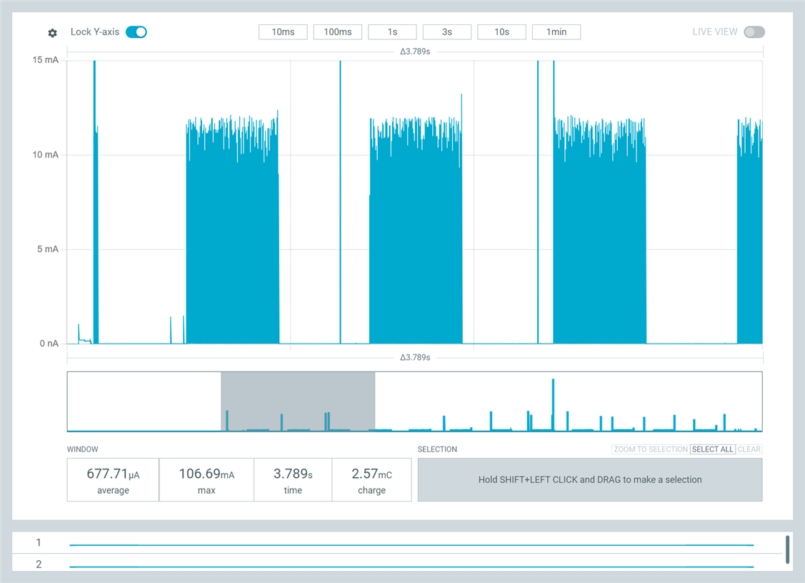
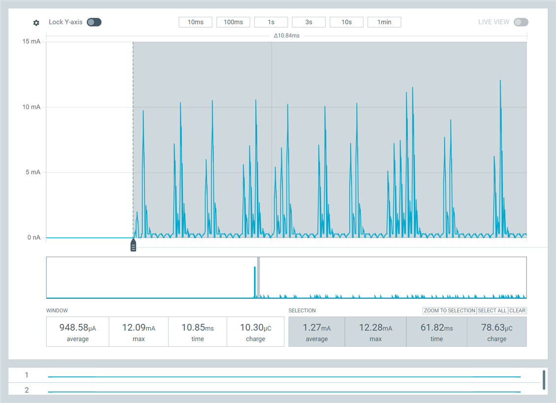
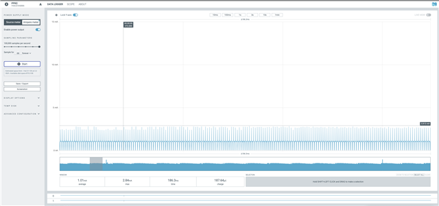
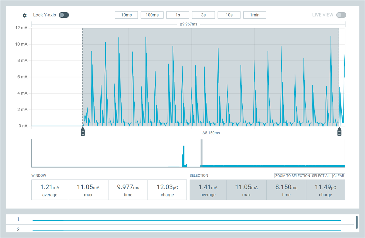
Figure 1 shows what we are consistently seeing on the nRF52811-based custom board using nRF Connect SDK and the code above. This figure shows a detail of power consumption at the end of the 100ms sleep and then after PWM is enabled. As you can see, power consumption is around 1.4 mA @ 3V, but even more strange are the huge, frequent, but irregular spikes up to 10 mA while PWM is running.

We see identical behavior if we continue to use nRF Connect SDK but eliminate PWM from the DTS and simply rework the test application to use the lower-level nrfx_pwm modules intead of the Zephyr clock_control driver.

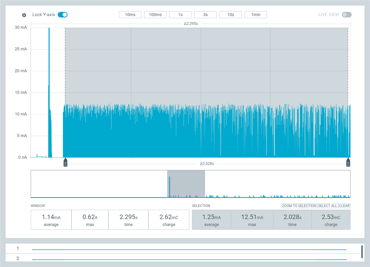
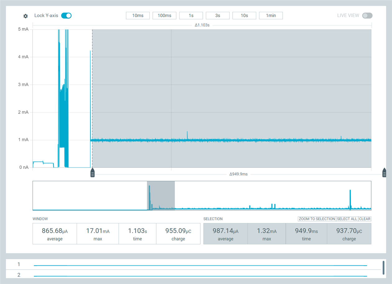
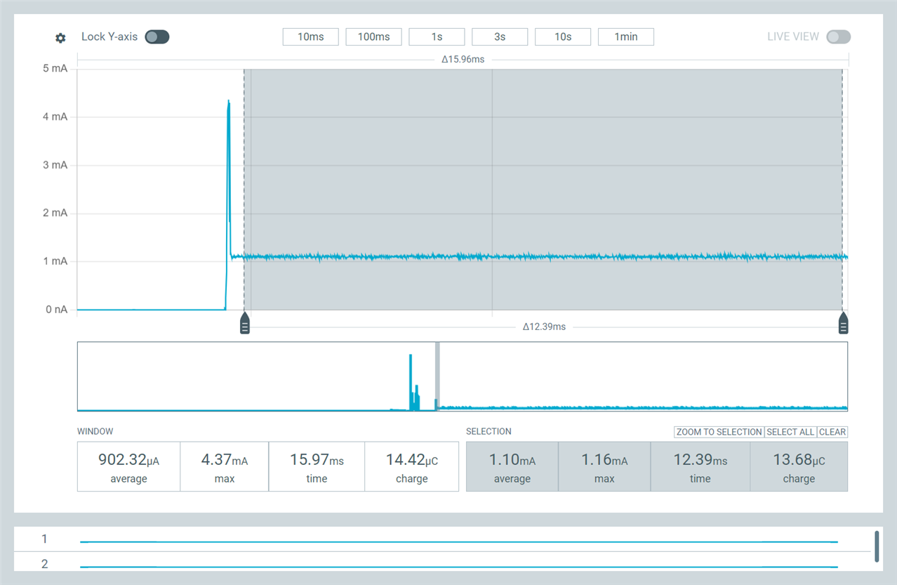
Figure 2, in contrast, shows what we are consistently seeing on teh nRF52811-based on custom board using nRF5 SDK and embOS RTOS and equivalent code based on the the nrfx_pwm driver. Power consumption is only 1.1 mA @ 3V and is very consistent once PWM is turned on, with no huge spikes up to 10 mA. This suggests a difference either in how nRF Connect SDK is configuring the PWM peripheral controller or a difference in how it is servicing PWM from interrupts or threads.

To rule out a possible problem with our board-specific DTS file, we then created a Zephyr build configuration that used the nRF52840dk_nRF52811 board configuration, but we still see the same problem: high PWM power consumptin and huge spikes in current draw.

When we ran that exact same build on a custom nRF52840-based board, however, we do not see the high PWM power consumption and huge spikes in current draw; the power consumption graph looks like Figure 2.

We also built the same DTS-based test code using v3.1.1 of the nRF Connect SDK and toolchain, but it exhibits identical high-power consumption and huge spikes on the nRF52811, so the problem doesn't appear to be limited to a specific version of the nRF Connect DK.

I should also mention that none of these builds enables USE_DMA_ISSUE_WORKAROUND or NRFX_PWM_NRF52_ANOMALY_109_WORKAROUND_ENABLED, in either nRF Connect SDK or nRF5 SDK.

Finally, we made an attempt to resolve this after we noticed that nrfx_pwm.c on the nRF Connect SDK differs in an important way from the nRF5 SDK version: if you pass NULL for the handler to nrfx_pwm_init() on nRF5 SDK, the PWM interrupt is not enabled, but it is always enabled on nrfx_pwm for nRF5 Connect SDK. Thinking this interrupt might be playing a role, we ported the nRF5 SDK version of nrfx_pwm to nRF Connect SDK to eliminate any differences in driver implementation, but we still experienced the high power consumption and huge spikes.

Based on sll of this, we're at a loss to explain what is causing the problem: the same hardware using the same driver code with the same configuration behaves very differently on nrF5 SDK with embOS than on nRF Connect SDK. It seems like it has to have something to do with some system-wide behavior or configuration for Zephyr, but then why don't we see it on the nRF52840?

I should mention that our nRF52811-based custom board is extremely simple, pretty much just an nRF52811 connected to power circuitry. In all tests above, we're using the DCDC regulator. The only unusual thing about this board is that it lacks an external LFCLK, and so our prj.conf for this test looks like this (our actual prj.conf is significantly larger):

CONFIG_SERIAL=n

CONFIG_NRFX_PWM0=y

CONFIG_CLOCK_CONTROL_NRF=y
CONFIG_CLOCK_CONTROL_NRF_K32SRC_RC=y
CONFIG_CLOCK_CONTROL_NRF_K32SRC_500PPM=y
CONFIG_CLOCK_CONTROL_NRF_K32SRC_XTAL=n
CONFIG_CLOCK_CONTROL_NRF_K32SRC_50PPM=n
CONFIG_CLOCK_CONTROL_NPCX_SUPP_APB4=n

Any guidance you can provide would be appreciated. Thank you!

Nathan Tennies

RC63_B25_V2_DEVKIT.dts

Parents
  • Hi,


    It almost looks like there is something asserting or reseting on your end? What does the log output look like?

    Here is the sample that I used for testing, which yielded this result in ppk2:


    And 3.2 MHz (HFINT sourced, which is why its a bit off on my end) output:


    Here's the sample as a .zip for your convenience:

    0488.blinky_pwm.zip


    I used nrf52dk/nrf52810 as the board for testing.


    Kind regards,

    Håkon

  • Thank you for your response.

    > It almost looks like there is something asserting or reseting on your end?

    We don't believe this is the case. Maybe I didn't make this clear, but when we see this high power consumption with huge current spikes after turning on PWM on the nRF52811 using nRF Connect SDK, we can see that the PWM output is working correctly on our digital logic analyzer, producing the required 3.2 MHz clock. So the MCU is definitely not resetting.

    We don't have support for printk logging via serial set up -- we've been using a custom logging mechanism based on Segger RTT -- and we don't have assertions enabled, so we don't think an assertion is causing this issue. But the point is, nothing is affecting the correct output of the PWM signal, despite the high power consumption and current spikes.

    Furthermore, in our actual application firmware, we turn on PWM for about 100ms toward the beginning our app -- and we see the same high power consumption and current spikes -- but our application continues to run correctly. So if there is a problem with a thread, it's definitely not the main thread.

    >I used nrf52dk/nrf52810 as the board for testing.

    As we indicated, when we built our test using the nrf52840dk_nrf52811 board, and we ran this code on our nRF52811-based custom board, we see the problem. Without making any modifications, if we run this on our nRF52840 board, we do not see the problem, even though the nRF52840 can be used to emulate the nRF52811. I believe there is something about how Zephyr is treating the actual nRF52811 -- even if the nrf52840dk_nrf52811 board definition is used -- that is different than how this works with the actual nRF52840.

    As an example of this, it just so happens we have an older version of the nRF52811 board we're using that is based on the nRF52810. Again, this board is essentially just an nRF52810 with power circuitry (it's a devkit we created with a daughterboard connector, so if we don't have the daughterboard connected, it's just the nRF52810 with no peripherals attached). 

    We took the code you provided and made a single modification to it, changing which pad was used for PWM output (to 0,14). We then created a build config for the nRF52dk_nrf52810, just as I assume you did (BTW, we always select "Optimize for Debugging" in the build config to prevent optimization). PWM output works as expected, but here's what the PPK2 output looks like:

    You can instantly see a dramatic difference between this and the capture you made on the nRF52DK. In your capture, you never see current spikes above maybe 1.3 mA once PWM was enabled, but here we're getting current spikes over 10 mA. In addition, the noise in your capture was evenly centered the 952 uA average, but in this capture from an actual nRF52810, we see spikes going down close to zero uA.

    Furthermore, I demonstrated that our code is continuing to run correctly even while this high power consumption and current spikes are occurring: I did this by modding your test code to turn PWM on for 500ms and then off for 500ms, looping forever. I see the expected output on the logic analyzer, and here's what I see in PPK2:

    Furthermore, you can see exactly how strange the behavior of the power consumption is if we zoom on the end of the 100ms delay and the start of PWM:


    I have spent a lot of time looking at PPK2 output from the nRF52840, nRF52810, and nRF52811 over the last several years using the nRF5 SDK, and I have never seen anything that looks like that when the MCU is in Sleep mode (as it should be in this case, after PWM is started). Furthermore, when I run the same code based on nRF5 SDK + embOS on this nRF52810 board, we again do not see this high power consumption or huge current spikes:

    It seems to me that there is something about the nRF Connect SDK implementation for the nRF52810 and nRF52811 that is not working properly, something that I think Nordic may be missing because you are using the nRF52832DK and nRF52840DK to emulate the nRF52810 and nRF52811.

    Please let me know what you think is happening. Thank you!

    Nathan Tennies

Reply
  • Thank you for your response.

    > It almost looks like there is something asserting or reseting on your end?

    We don't believe this is the case. Maybe I didn't make this clear, but when we see this high power consumption with huge current spikes after turning on PWM on the nRF52811 using nRF Connect SDK, we can see that the PWM output is working correctly on our digital logic analyzer, producing the required 3.2 MHz clock. So the MCU is definitely not resetting.

    We don't have support for printk logging via serial set up -- we've been using a custom logging mechanism based on Segger RTT -- and we don't have assertions enabled, so we don't think an assertion is causing this issue. But the point is, nothing is affecting the correct output of the PWM signal, despite the high power consumption and current spikes.

    Furthermore, in our actual application firmware, we turn on PWM for about 100ms toward the beginning our app -- and we see the same high power consumption and current spikes -- but our application continues to run correctly. So if there is a problem with a thread, it's definitely not the main thread.

    >I used nrf52dk/nrf52810 as the board for testing.

    As we indicated, when we built our test using the nrf52840dk_nrf52811 board, and we ran this code on our nRF52811-based custom board, we see the problem. Without making any modifications, if we run this on our nRF52840 board, we do not see the problem, even though the nRF52840 can be used to emulate the nRF52811. I believe there is something about how Zephyr is treating the actual nRF52811 -- even if the nrf52840dk_nrf52811 board definition is used -- that is different than how this works with the actual nRF52840.

    As an example of this, it just so happens we have an older version of the nRF52811 board we're using that is based on the nRF52810. Again, this board is essentially just an nRF52810 with power circuitry (it's a devkit we created with a daughterboard connector, so if we don't have the daughterboard connected, it's just the nRF52810 with no peripherals attached). 

    We took the code you provided and made a single modification to it, changing which pad was used for PWM output (to 0,14). We then created a build config for the nRF52dk_nrf52810, just as I assume you did (BTW, we always select "Optimize for Debugging" in the build config to prevent optimization). PWM output works as expected, but here's what the PPK2 output looks like:

    You can instantly see a dramatic difference between this and the capture you made on the nRF52DK. In your capture, you never see current spikes above maybe 1.3 mA once PWM was enabled, but here we're getting current spikes over 10 mA. In addition, the noise in your capture was evenly centered the 952 uA average, but in this capture from an actual nRF52810, we see spikes going down close to zero uA.

    Furthermore, I demonstrated that our code is continuing to run correctly even while this high power consumption and current spikes are occurring: I did this by modding your test code to turn PWM on for 500ms and then off for 500ms, looping forever. I see the expected output on the logic analyzer, and here's what I see in PPK2:

    Furthermore, you can see exactly how strange the behavior of the power consumption is if we zoom on the end of the 100ms delay and the start of PWM:


    I have spent a lot of time looking at PPK2 output from the nRF52840, nRF52810, and nRF52811 over the last several years using the nRF5 SDK, and I have never seen anything that looks like that when the MCU is in Sleep mode (as it should be in this case, after PWM is started). Furthermore, when I run the same code based on nRF5 SDK + embOS on this nRF52810 board, we again do not see this high power consumption or huge current spikes:

    It seems to me that there is something about the nRF Connect SDK implementation for the nRF52810 and nRF52811 that is not working properly, something that I think Nordic may be missing because you are using the nRF52832DK and nRF52840DK to emulate the nRF52810 and nRF52811.

    Please let me know what you think is happening. Thank you!

    Nathan Tennies

Children
  • Hi Nathan,


    ntennies said:
    something that I think Nordic may be missing because you are using the nRF52832DK and nRF52840DK to emulate the nRF52810 and nRF52811.

    Sorry for not being explicit. Even when the board variant is the nRF52-DK; I did run tests on a nRF52810 target.

    And the below screenshots are from running the same fw as previously shared, on a nRF52811 target.

    ntennies said:
    As we indicated, when we built our test using the nrf52840dk_nrf52811 board, and we ran this code on our nRF52811-based custom board, we see the problem. Without making any modifications, if we run this on our nRF52840 board, we do not see the problem, even though the nRF52840 can be used to emulate the nRF52811. I believe there is something about how Zephyr is treating the actual nRF52811 -- even if the nrf52840dk_nrf52811 board definition is used -- that is different than how this works with the actual nRF52840.

    If I understand you correctly, you are pointing towards this define in nrf52840dk board definition:

    https://github.com/nrfconnect/sdk-zephyr/blob/ncs-v3.1.0/boards/nordic/nrf52840dk/CMakeLists.txt#L9

    or the equivalent for nrf52dk/nrf52810:

    https://github.com/nrfconnect/sdk-zephyr/blob/ncs-v3.1.0/boards/nordic/nrf52dk/CMakeLists.txt#L7


    Can you please share your exact changes if this issue is related to firmware behavior?

    ntennies said:

    As an example of this, it just so happens we have an older version of the nRF52811 board we're using that is based on the nRF52810. Again, this board is essentially just an nRF52810 with power circuitry (it's a devkit we created with a daughterboard connector, so if we don't have the daughterboard connected, it's just the nRF52810 with no peripherals attached). 

    We took the code you provided and made a single modification to it, changing which pad was used for PWM output (to 0,14). We then created a build config for the nRF52dk_nrf52810, just as I assume you did (BTW, we always select "Optimize for Debugging" in the build config to prevent optimization). PWM output works as expected, but here's what the PPK2 output looks like:

    Are you testing with the PPK2 in ampere meter mode, or in source mode?

    ntennies said:
    You can instantly see a dramatic difference between this and the capture you made on the nRF52DK. In your capture, you never see current spikes above maybe 1.3 mA once PWM was enabled, but here we're getting current spikes over 10 mA. In addition, the noise in your capture was evenly centered the 952 uA average, but in this capture from an actual nRF52810, we see spikes going down close to zero uA.

    The issue is not the average, but the dynamic form of the current profile?

    It does sound like there's less capacitance in your custom board, as compared to a DK. If you add a capacitor, lets say a 100 uF, does this improve the peaks?


    I also see smaller differences when using ampere mode:

    As compared to source meter:


    I believe the direct reason why you are seeing a difference in the dynamic measurement is due to LDO vs. DCDC. Try disabling the DCDC:

    &reg {
    	regulator-initial-mode = <NRF5X_REG_MODE_LDO>;
    };


    Then the ampere mode will look like this due to less dynamic current consumption (but higher overall current consumption..) draw from the chip:


    Kind regards,

    Håkon

  • Håkon, thank you for your response.

    While the things you've highlighted might explain why you are not seeing the problem we are seeing when you test this on the nRF52810, that doesn't address our core question: why are we seeing this dramatic difference in behavior between nRF Connect SDK and nRF5 SDK + embOS, running on the same hardware, and being tested in exactly the same way?

    The difference in behavior here has to be caused by a difference in what software is doing. That's the only explanation.

    But the problem here is that PWM used for clock generation does not require software to do anything once the PWM is configured and started. PWM clock generation happens entirely in hardware on the nRF52 MCU. It doesn't require interrupts to service anything (correct?).

    So this means that if the PWM peripheral controller is configured and started in exactly the same way on nRF Connect SDK as on nRF5 SDK, we should see the hardware produce exactly the same power consumption profile on the same hardware tested in the same way. Correct? 

    But we're not, so I think there are only three general possibilities here:

    1. There is a difference in PWM peripheral controller configuration between nRF Connect SDK and nRF5 SDK, even when we use the nrfx_pwm module directly in both cases with identical configuration (as we have tried). As I mentioned, we attempted to address this possibility by porting the version of nrfx_pwm from nRF5 SDK -> nRF Connect SDK, and we still the same difference in behavior on nRF Connect SDK. So we don't believe this is due to a difference in PWM peripheral controller configuration.
    2. There is a difference in the configuration of some other part of the MCU:
      1. We don't believe there is a difference in DCDC regulator configuration. We are calling sd_power_dcdc_mode_set(NRF_POWER_DCDC_ENABLE) on the nRF5 SDK version of the app, and all of these builds have regulator-initial-mode = < 0x1 > set in the zephyr.dts, which means DCDC is enabled (correct?)
      2. We have a call to sd_power_mode_set(NRF_POWER_MODE_LOWPWR) in our nRF5 SDK code, so I added nrf_power_task_trigger(NRF_POWER, NRF_POWER_TASK_LOWPWR) to our nRF Connect SDK test, but I we still have the high, spikey power consumption.
      3. We have a call to SCB->SCR |= SCB_SCR_SLEEPDEEP_Msk;in our nRF5 SDK code, so I added it to our nRF Connect SDK test, but I we still have the high, spikey power consumption.
      4. Are there other MCU settings that could be affecting system power behavior when PWM is enabled? For instance, other power regulator settings?
    3. There is a difference in the behavior of non-PWM interrupts or tasks other than main while PWM is running. In other words, enabling PWM is causing some non-PWM interrupts to fire periodically or a system thread is running periodically. Does VSCode / Zephyr provide a way to monitor which interrupts and threads are running so we can rule out this option?

    Our goal here is to understand why we're seeing this fundamental difference in power consumption behavior while PWM is enabled between nRF Connect SDK and nRF5 SDK + embOS, while running on the same hardware, and while being tested in an identical way.

    And this isn't simply academic. We are seeing a significant increase in power consumption on average on the version of our app built on nRF Connect SDK than we are on the version built with nRF5 SDK + embOS, even though we see lower power consumption in the nRF Connect SDK version in some phases of our code. The only place we are seeing increased power consumption is when PWM is running, which led us to focus on this difference in behavior between the two software platforms.

  • Hi,


    I just want to re-iterate:

    ntennies said:
    You can instantly see a dramatic difference between this and the capture you made on the nRF52DK. In your capture, you never see current spikes above maybe 1.3 mA once PWM was enabled, but here we're getting current spikes over 10 mA. In addition, the noise in your capture was evenly centered the 952 uA average, but in this capture from an actual nRF52810, we see spikes going down close to zero uA.

    All my posted measurements are performed on actual nRF52810 and nRF52811 silicon, mounted on a nRF52-DK.


    And please note that spikes are in-nature, expected, from any nRF5x device, due to the regulator refresh mode.

    This is entered in various states of sleep, automatically by the hardware, in which "regulator refresh mode" will monitor the voltage output over a external capacitor.

    When the voltage level goes to whatever "minimum value" is required for the sleep mode, the hardware will automatically re-charge the capacitor. This will then emit itself as a current spike in the mA area.

    PPK2 will have a hard time to accurately show the exact spike (average current will be fine), as you are then switching between two (or even more) accuracy modes within the PPK2, which are listed here:

    https://docs.nordicsemi.com/bundle/ug_ppk2/page/UG/ppk/ppk_measure_accuracy.html


    PPK2 source meter is usually more accurate.


    Q1: Could you verify your findings with another multimeter source?


    This is to ensure this is not artefacts of the PPK2 switching levels or something similar.

    Please, with a multimeter or something like that, measure the avg. current (or dynamic current drawn), and compare the exact same test case against ppk2.

    PPK2 can, in some scenarios, have issues with certain chipsets/PCs, like the AM4/AM5 platform:

    https://github.com/NordicSemiconductor/pc-nrfconnect-ppk/issues/318

    Such a data loss is less noticeable if the current draw is constant (+/ small variations)


    In your setup, that you explicitly state is equal in terms of nRF setup, however; there is a difference in avg measured current.

    It is important to establish what the expected current is for both your scenarios.


    Q2: Did you run the firmware that I shared with you?

    Please share plots and also; please share any changes that you performed on the firmware to replicate any unwanted behavior (as a .diff or .zip).


    Q3: Can you please address the former questions, related to your test setup?

    Håkon Alseth said:

    The issue is not the average, but the dynamic form of the current profile?

    It does sound like there's less capacitance in your custom board, as compared to a DK. If you add a capacitor, lets say a 100 uF, does this improve the peaks?

    Håkon Alseth said:

    Can you please share your exact changes if this issue is related to firmware behavior?


    Q4: Do you use PPK2 in source meter mode, or in ampere meter mode?

    To address your comments: 

    ntennies said:
    There is a difference in PWM peripheral controller configuration between nRF Connect SDK and nRF5 SDK, even when we use the nrfx_pwm module directly in both cases with identical configuration (as we have tried). As I mentioned, we attempted to address this possibility by porting the version of nrfx_pwm from nRF5 SDK -> nRF Connect SDK, and we still the same difference in behavior on nRF Connect SDK. So we don't believe this is due to a difference in PWM peripheral controller configuration.

    PWM hardware module does not draw additional current if the hardware is setup equal in both projects.

    Please see my other comments, such as the above comments about the ppk2 in general, as well as which mode you placed the PPK2 into, and please answer questions that are asked.


    ntennies said:
    We don't believe there is a difference in DCDC regulator configuration. We are calling sd_power_dcdc_mode_set(NRF_POWER_DCDC_ENABLE) on the nRF5 SDK version of the app, and all of these builds have regulator-initial-mode = < 0x1 > set in the zephyr.dts, which means DCDC is enabled (correct?)

    Correct: https://github.com/nrfconnect/sdk-zephyr/blob/ncs-v3.1.0/include/zephyr/dt-bindings/regulator/nrf5x.h#L22

    And as per my former measurements (and above explanation on how nRF regulators work); you shall see spikes in sleep modes.

    ntennies said:
    We have a call to sd_power_mode_set(NRF_POWER_MODE_LOWPWR) in our nRF5 SDK code, so I added nrf_power_task_trigger(NRF_POWER, NRF_POWER_TASK_LOWPWR) to our nRF Connect SDK test, but I we still have the high, spikey power consumption.

    This is the default mode of the nRF52 device, so unless it was explicitly overridden, this shall not need to be set.

    ntennies said:
    We have a call to SCB->SCR |= SCB_SCR_SLEEPDEEP_Msk;in our nRF5 SDK code, so I added it to our nRF Connect SDK test, but I we still have the high, spikey power consumption.

    This is not required in our devices, as per this thread:

     RE: nrf_pwr_mgmt_run impact of SCB_SCR_SLEEPDEEP_Msk 


    ntennies said:
    Are there other MCU settings that could be affecting system power behavior when PWM is enabled? For instance, other power regulator settings?

    Short answer is "not directly" - long answer is that some modules will place the SoC in a different internal power mode, but again; this highly depend on what other feature(s) are currently active in your test setup.

    HFXO running? Radio running? SAADC running?

    ntennies said:
    And this isn't simply academic. We are seeing a significant increase in power consumption on average on the version of our app built on nRF Connect SDK than we are on the version built with nRF5 SDK + embOS, even though we see lower power consumption in the nRF Connect SDK version in some phases of our code. The only place we are seeing increased power consumption is when PWM is running, which led us to focus on this difference in behavior between the two software platforms.

    I believe we need to take a step back, and evaluate external factors to the measurements, to rule out other potential error sources, as per the above questions.

    All tests that I have performed, on target silicon nRF52810/811, are unable to reproduce the scenario, which indicate that this is either an artifact of the measurement itself, or some other issue related to setup difference.

    As previously pointed out, the way you measure is relevant, and especially when testing on custom board(s), as there will be differences in external decoupling and overall power draw as compared to a DK from us.


    Kind regards,

    Håkon

  • Håkon,

    Thank you again for your help on this. I wanted to close the loop on it.

    We did a comparison of nRF5211 registers settings between the nRF5 SDK and the Zephyr version and were able to source of the difference in behavior, which was due to a few things:

    • First, the difference in behavior was caused by a code error on the nRF5 SDK version of the code, which was that although we were enabling the DCDC regulator, we were doing so incorrectly (that call was accidentally getting made _before_ the SoftDevice had been inited). With the DCDC regulator enabled, we were seeing the same high, spikey power consumption on nRF5 SDK that we were seieng on Zephyr.
    • Of course, power consumption with DCDC enabled will be more spikey, but should be lower. We think the magnitude of the spikes and therefore the higher power consumption were due entirely auto-ranging artifacts on the nRF5 SDK. When we applied caps to the board, obviously the power spikes went away but also the power consumption ended up being lower than we DCDC disabled, as expected.

    So we're all good here.

Related