Hello,
I've been developing an nRF52840 on a custom PCB for ~1 month now, and my environment was working previously. After updating my version of Jlink and installing other python VS code extensions, code that was once building, flashing, and running successfully now will build, flash, and verify, but will never run. No RTT, uart serial, or GPIO are functioning on the board and I can't get any configuration or environment changes to fix the problem.
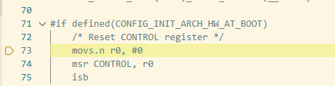
I have gone back to attempting to build and run the blinky example (using a GPIO that I can easily measure on my board) so that I can get the code to run and execute main at all.
When I do this, I still get the same successful building and flashing but the code seems to never reach main.
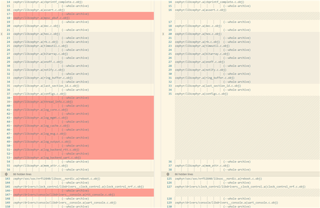
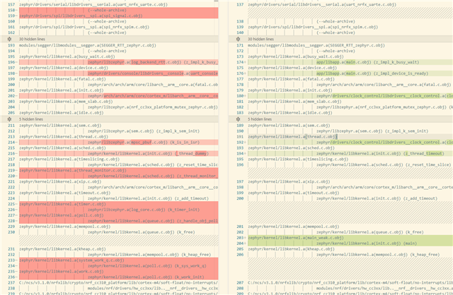
I have noticed that under my build outputs, I see the following: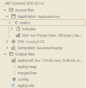
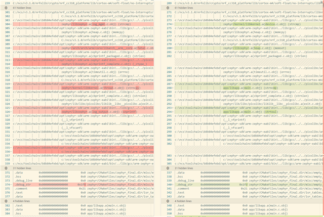
I have a project for another target that compiles & runs successfully, and i noticed that under main.c, the size (bss, text, and data) were much larger and none were 0. the size of zephyr.elf seems much more appropriate - but when I hit flash it flashes using the file merged.hex.
I was wondering if anyone could shed light on why main.c would be so small (it seems like parts of zephyr or my program are not linking) and the difference between flashing zephyr.elf and merged.hex.
relevant files:
prj.conf: 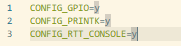
(at various points, I tried to also include logging, RTT, or uart - none of which changed the behavior)
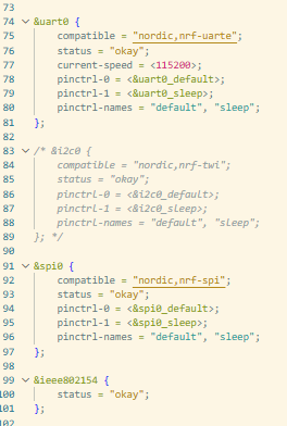
custom_board.dts: (2 images)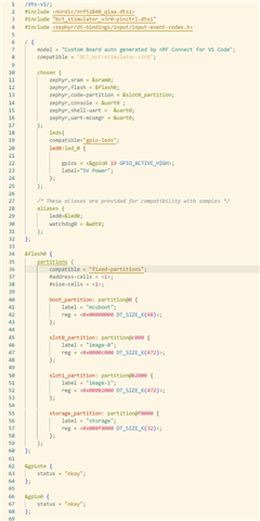
main.c:
Build output: 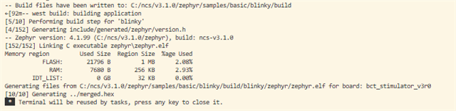
Flash output: 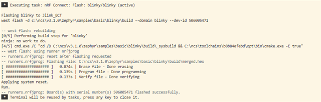
The entire board is only pulling 8 mA, which is much too low for me to think that any code is executing on the nRF52840-QIAA.
Thank you, let me know if anyone else has had a similar issue!