SLM Shell issue on nRF52840dk and nRF9151DK SLM

Hi,

I am trying to communicate with Serial LTE Modem application running on nRF9151DK through SLM Shell sample running on nRF52840DK.

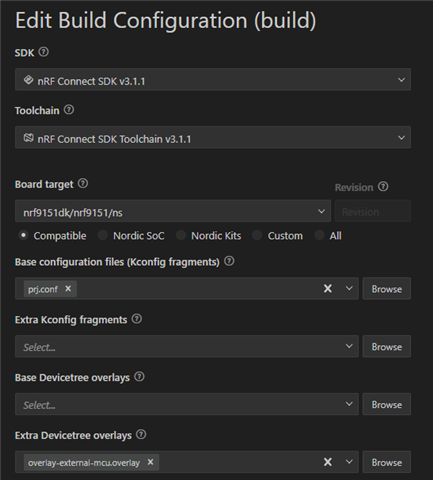
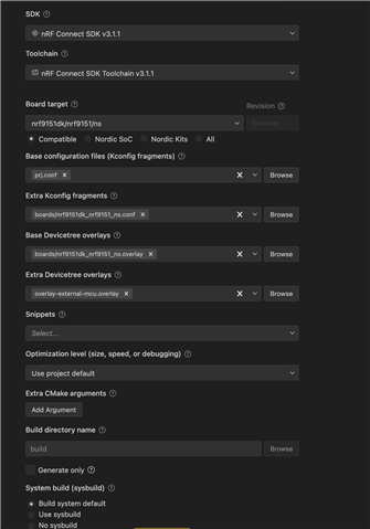
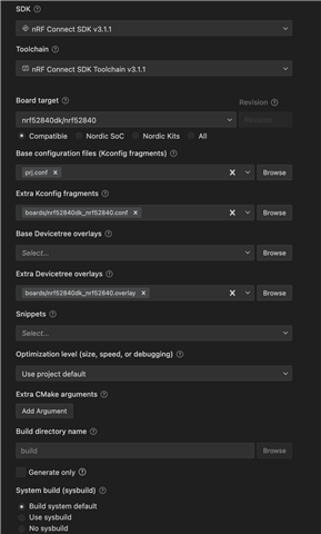
I am using nrf connect in vscode, and have followed the instructions in:

https://docs.nordicsemi.com/bundle/ncs-3.0.2/page/nrf/applications/serial_lte_modem/doc/slm_description.html#requirements

I have couple of issues on both sides:

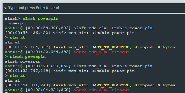
- On the slm-shell, when sending a simple "at" command, I receive TX Abort, I tried increasing the timeout, got same result:

*** Booting nRF Connect SDK v3.1.1-e2a97fe2578a ***
*** Using Zephyr OS v4.1.99-ff8f0c579eeb ***
[00:00:00.320,373] <inf> app: SLM Shell starts on nrf52840dk
[00:00:00.320,434] <inf> mdm_slm: UART baud: 115200 d/p/s-bits: 3/0/1 HWFC: 1
uart:~$ > slm at
slm at
[00:01:23.960,601] <wrn> mdm_slm: UART_TX_ABORTED, dropped: 4 bytes
uart:~$ [00:01:33.860,687] <err> mdm_slm: timeout

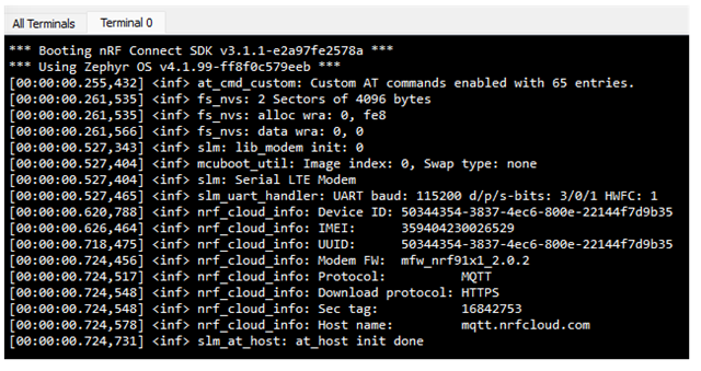
- On the modem side, I am using J-link RTT Viewer, but cannot capture any logs after the initial connection:

[00:00:00.252,655] <err> spi_nor: Device id 90 ca 33 does not match config c8 65 19
*** Booting nRF Connect SDK v3.1.1-e2a97fe2578a ***
*** Using Zephyr OS v4.1.99-ff8f0c579eeb ***
[00:00:00.253,662] <inf> at_cmd_custom: Custom AT commands enabled with 64 entries.
[00:00:00.254,119] <dbg> slm: main: RR: 0x00000001
[00:00:00.260,833] <inf> fs_nvs: 2 Sectors of 4096 bytes
[00:00:00.261,169] <inf> fs_nvs: alloc wra: 0, fe8
[00:00:00.261,505] <inf> fs_nvs: data wra: 0, 0
[00:00:00.528,778] <inf> slm: lib_modem init: 0
[00:00:00.529,144] <inf> mcuboot_util: Image index: 0, Swap type: none
[00:00:00.529,510] <inf> slm: Serial LTE Modem
[00:00:00.529,846] <inf> slm_uart_handler: UART baud: 115200 d/p/s-bits: 3/0/1 HWFC: 1
[00:00:00.623,565] <inf> nrf_cloud_info: Device ID: 50344354-3837-4ec6-800e-22144f7d9b35
[00:00:00.629,241] <inf> nrf_cloud_info: IMEI: 359404230026529
[00:00:00.721,588] <inf> nrf_cloud_info: UUID: 50344354-3837-4ec6-800e-22144f7d9b35
[00:00:00.727,569] <inf> nrf_cloud_info: Modem FW: mfw_nrf91x1_2.0.2
[00:00:00.727,966] <inf> nrf_cloud_info: Protocol: MQTT
[00:00:00.728,302] <inf> nrf_cloud_info: Download protocol: HTTPS
[00:00:00.728,668] <inf> nrf_cloud_info: Sec tag: 16842753
[00:00:00.729,034] <inf> nrf_cloud_info: Host name: mqtt.nrfcloud.com
[00:00:00.729,553] <dbg> slm_at_host: slm_at_send_indicate: TX
52 65 61 64 79 0d 0a |Ready..
[00:00:00.730,621] <inf> slm_at_host: at_host init done

Can you please advise how to resolve these issues?

Thanks

Parents
  • Hello, could you please provide more information on you connection between the nRF9151DK and nRF52840?

    I will try to reproduce the issue on my side.

    Kind regards,
    Øyvind

  • Hello,

    Thanks for your prompt reply.

    I am following the guide in 'Connecting with an external MCU' in the above link, please see below the connection between boards:

    nRF52 Series DK

    nRF91 Series DK

    UART TX P1.02

    UART RX P0.11

    UART RX P1.01

    UART TX P0.10

    UART CTS P1.06

    UART RTS P0.12

    UART RTS P1.07

    UART CTS P0.13

    GPIO OUT P0.11

    GPIO IN P0.31

    GPIO IN P0.13

    GPIO OUT P0.30

    GPIO GND

    GPIO GND

    I have changed the config to:

    CONFIG_SLM_POWER_PIN=31

    CONFIG_SLM_INDICATE_PIN=30

    No changes on the original codes, uart2 on nRF9151 and uart1 on nRF52840 are used as ncs-slm-uart.

    Regards,

    Roya

  • Thanks for clarifying. I´m having issues with building this project out of the box. Could you please provide the steps you used to build serial LTE modem application? Did you build with -DDTC_OVERLAY_FILE="overlay-external-mcu.overlay"?

    Kind regards,
    Øyvind

  • Hello,

    I built the serial LTE modem with this configuration:

    However, I had issues with building SLM_Shell application.

    I was assuming it would automatically merge nrf52840dk_nrf52840.conf with prj.conf, but it didn't. I received error regarding SLM_POWER_PIN which by default is -1 and in that file assigned to pin 11.

    I had to copy the content of that file to prj.conf to avoid the error, so the new prj.conf was:

    CONFIG_STACK_SENTINEL=y
    CONFIG_MAIN_STACK_SIZE=4096
    CONFIG_HEAP_MEM_POOL_SIZE=8192
    CONFIG_SYSTEM_WORKQUEUE_STACK_SIZE=2048

    CONFIG_LOG=y
    CONFIG_LOG_BACKEND_UART=y
    CONFIG_CONSOLE=y
    CONFIG_UART_CONSOLE=y
    CONFIG_SHELL=y
    CONFIG_SHELL_WILDCARD=n
    CONFIG_SHELL_ARGC_MAX=40
    CONFIG_SHELL_CMD_BUFF_SIZE=1024
    CONFIG_SHELL_STACK_SIZE=2048
    CONFIG_SHELL_LOG_BACKEND=y

    CONFIG_SERIAL=y
    CONFIG_UART_ASYNC_API=y

    CONFIG_MODEM_SLM=y
    CONFIG_MODEM_SLM_SHELL=y
    CONFIG_MODEM_SLM_LOG_LEVEL_INF=y

    CONFIG_ASSERT=y

    CONFIG_NRFX_UARTE1=y
    CONFIG_UART_1_INTERRUPT_DRIVEN=n
    CONFIG_UART_1_ASYNC=y
    CONFIG_MODEM_SLM_POWER_PIN=11
    CONFIG_MODEM_SLM_INDICATE_PIN=13
    Regards,
    Roya
  • Hello Roya, 

    [00:01:23.960,601] <wrn> mdm_slm: UART_TX_ABORTED, dropped: 4 bytes
    uart:~$ [00:01:33.860,687] <err> mdm_slm: timeout

    I was able to reproduce this issue. But on my side it turned out to be wrong wiring. Double checked my wires and had flipped rx and tx on one side. Now I can send the command slm at and get response OK. Also, slmsh powerpin works as expected. 

    uart:~$ > slmsh powerpin
    slmsh powerpin
    uart:~$ [00:12:25.233,245] <inf> mdm_slm: Enable power pin
    [00:12:25.333,404] <inf> mdm_slm: Disable power pin
    s> slm at
    lm at
    [00:12:33.742,950] <wrn> mdm_slm: UART_TX_ABORTED, dropped: 4 bytes
    > slmsh powerpin
    uart:~$ slmsh powerpin
    uart:~$ [00:12:43.643,005] <err> mdm_slm: timeout
    [00:12:43.645,233] <inf> mdm_slm: Enable power pin
    [00:12:43.745,361] <inf> mdm_slm: Disable power pin
    [00:12:44.954,803] <inf> app: Data received (len=7): Ready
    
    > slm at
    slm at
    Ready
    
    OK

    Here is my build configuration in VS Code for both projects:

    SLM 

    SLM Shell

    Kind regards,
    Øyvind

  • Hello Øyvind,

    Thank you for providing the build configurations.

    I have double-checked all connections, also recreated new applications for both, but still stuck.

    - SLM_shell TX aborts:

    - As for SLM, I am not receiving the Ready message after toggling the power pin:

    It seems J-link RTT is somehow disconnected, can't figure out the reason.

    Regards,

    Roya

Reply
  • Hello Øyvind,

    Thank you for providing the build configurations.

    I have double-checked all connections, also recreated new applications for both, but still stuck.

    - SLM_shell TX aborts:

    - As for SLM, I am not receiving the Ready message after toggling the power pin:

    It seems J-link RTT is somehow disconnected, can't figure out the reason.

    Regards,

    Roya

Children
  • Hello Øyvind,

    I re-installed the SDK, toolchain, and SEGGER, running more tests. The SLM-shell seems to work as expected, please see the logs below:

    However, no changes on the RTT viewer, same results as my last post. I tried both J-Link v8.88 and v8.76.

    - I was wondering if I can use uart backend instead of RTT, but I am confused which uart peripheral is used for this option, if it is uart0, how TX/RX on pins 11 and 12 are sent to console?

    Can you please clarify it?
    Thanks,
    Roya
  • Hi Roya, 

    _rd said:
    I re-installed the SDK, toolchain, and SEGGER, running more tests. The SLM-shell seems to work as expected, please see the logs below:

    Thanks for the information. Looks like this has solved the issue with UART between the devices at least.

    _rd said:
    However, no changes on the RTT viewer, same results as my last post. I tried both J-Link v8.88 and v8.76.

    This is strange. One thing that our developers point to is to test with the newest Serial Modem application. This is the newest official application we´ll be using going forward: Serial Modem application for nRF91-based devices. Could you give that a try? The Serial LTE Modem is now deprecated in v3.2.0 in nRF Connect SDK. 

    _rd said:

    I was wondering if I can use uart backend instead of RTT, but I am confused which uart peripheral is used for this option, if it is uart0, how TX/RX on pins 11 and 12 are sent to console?

    Have a look at this documentation on Logging. It should be possible to use UART instead of RTT. 

    Kind regards,
    Øyvind

Related