Could not make SPI HCI work on Zephyr 4.3.0 with nRF54L15

Hello, I'm trying to make samples/bluetooth/hci_spi work on my nRF54L15-DK however I encounter some issues My device tree overlay is as followed:

&pinctrl {
	spi21_default_alt: spi21_default_alt {
		group1 {
			psels = <NRF_PSEL(SPIS_SCK, 1, 11)>,
				<NRF_PSEL(SPIS_MOSI, 1, 12)>,
				<NRF_PSEL(SPIS_MISO, 1, 13)>,
				<NRF_PSEL(SPIS_CSN, 1, 9)>;
		};
	};
};

&spi21 {
	compatible = "nordic,nrf-spis";
	status = "okay";
	def-char = <0x75>;
	pinctrl-0 = <&spi21_default_alt>;
	pinctrl-names = "default";
	/delete-property/ rx-delay-supported;
	/delete-property/ rx-delay;

	bt-hci@0 {
		compatible = "zephyr,bt-hci-spi-slave";
		reg = <0>;
		irq-gpios = <&gpio1 8 (GPIO_ACTIVE_HIGH | GPIO_PULL_DOWN)>;
	};
};

/ {
	aliases {
		/delete-property/ sw0;
		/delete-property/ sw1;
		/delete-property/ sw2;
		/delete-property/ sw3;
		/delete-property/ mcuboot-button0;
	};
	/delete-node/ buttons;
};
/delete-node/ &spi00;
/delete-node/ &spi30;
/delete-node/ &spi20;
/delete-node/ &spi22;

&uart30 {
	status = "disabled";
};

I know that spi21.def-char should be <0x00> however for my test purpose it helps me to diagnose my SPI connection problem.

I also deleted all SPI devices and all buttons to prevent any conflict with development kit hardware

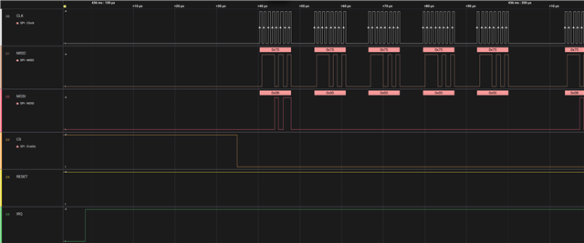
When I try to start the SPI communication with it I get the following when all pins are plugged.

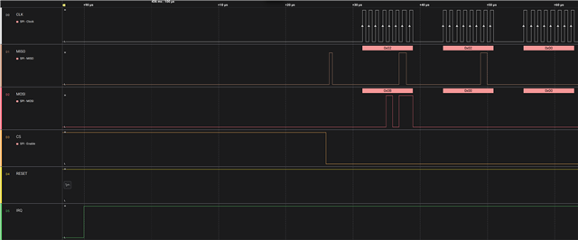
If I unplug CS and plug it directly to ground I get the following result:

What I find strange is that in the case were all pins are plugged the nRF54L15 try to send on MISO data when CS goes data even without any clock.
The first few bytes send by the nRF54L15 should be 04 ff 02 01 00
I also check with an oscilloscope but the signals are very clear.
Additionally I had to set my board on 3.3V as the SPI Master use this voltage.
Is there something I missed ?
Cordially,
Robyn
  • Hi Robyn, 

    Sorry for the late reply.

    My understanding here is that the slave firmware is doing everything it is supposed to do. The problem is, with the SPI master firmware. It is not finishing the two-phase handshake that the sample code is expecting from the Zephyr HCI-SPI code and our SPI master. The Zephyr HCI-SPI code is waiting for this handshake to be completed by our SPI master.

    In zephyr/samples/bluetooth/hci_spi/src/main.c the controller sends data to the host through spi_send() (lines 103‑148). The TX thread (bt_tx_thread, lines 150‑246) loops forever doing 5‑byte header exchanges with the host. Only when it sees the host issue a READ request (header_master[0] == SPI_READ/0x0B) does it release sem_spi_tx, so that spi_send() can run its own header exchange and then push the payload. The Nordic HCI SPI transport always needs two transactions where the chip select's low, for every single packet of the Nordic Zephyr HCI SPI transport.

    The master asserts CS, clocks out five bytes, and reads the slave header (byte 0 = READY_NOW/0x02, byte 3 = payload length). Once those five bytes are in, CS must go high so the slave can prepare the payload. When the payload is ready the slave raises Interrupt Request. The master then makes Chip Select active again sends a 0x0B which means read on the Master Out Slave In line and clocks out the payload bytes which are 04 ff 02 01 00, for the initialized event. Only after this second transfer happens the slave drops Interrupt Request. Goes back to idle state waiting for the next command.

    When you look at the Saleae captures you see that the master is keeping the Chip Select low. It is sending the bytes 0x0B. Some extra bytes, but it never lets go of the line between the header and the payload. This means the slave gets stuck, in the header state and never moves on. The function spi_send gets stuck in a loop waiting for something to happen. The Interrupt line just stays high. All you see on the MISO line is the header byte, which's either 0x02 or the test character 0x75 repeating over and over. When the Computer System is grounded it makes the Serial Peripheral Interface System peripheral send out the default character all the time. This is what the Serial Peripheral Interface System peripheral should be doing when it is not busy with a request from the Computer System. The Computer System and the Serial Peripheral Interface System peripheral work together, in this way.

    So thinking about how to move forward with this.

    Your master needs to use the Zephyr BT SPI host driver, which's the Zephyr BT SPI host driver. The Zephyr BT SPI host driver already has what you need it has the two-step handshake, with the CS toggling and it handles the IRQ correctly.

    If you still want to do bit-banging you have to do it right. First you have to read the 5-byte header then you have to deassert the CS then you have to wait for the IRQ then you have to reassert the CS and send 0x0B to get the payload from the Zephyr BT SPI host driver.

    To make sure everything works correctly we need to keep the IRQ wiring the same as it's in the devicetree. This means it should be active-high, with a pull-down.

    The master has to pay attention to that line. It should only start the transaction when the IRQ actually goes high. We are talking about the IRQ so the master needs to wait for the IRQ to go high before it starts the next transaction, which is the second transaction.

    When you are working with the nRF54L15 you have to make sure that each SPIS instance has its own DMA buffer region defined. You do this by using the memory-regions option and setting it to the cpuapp_dma_region. If you do not do this the spi_transceive function will fail every time even before it gets to the part. This is something you need to do for each SPIS instance on the nRF54L15.

    Once the master follows the handshake, the vendor event should come.

  • Hi,

    Thank you for your feedback Slight smile

    After some investigation I got some news.

    The communication broke apart when using the  "zephyr,bt-hci-spi" driver for the master in front of the example spi_hci with the driver "zephyr,bt-hci-spi-slave" for the slave.

    1. On the slave, in file zephyr/samples/bluetooth/hci_spi/src/main.c in function bt_tx_thread prepare the following payload to be transferred and wait for transfer:
      { READY_NOW, SANITY_CHECK, 0x00, 0x00, 0x00 }
    2. On the host bt_enable which goes into zephyr/drivers/bluetooth/hci/spi.c and once in bt_spi_rx_thread cause it to call 
      bt_spi_get_header(SPI_READ, &size)

      Preparing the following payload to be transferred

      { SPI_READ, 0x00, 0x00, 0x00, 0x00 }
    3. On the host bt_spi_get_header start the transfer which puts CS low and transceive 5 bytes
    4. The slave receives the host message but cannot leave spi_context_wait_for_completion before CS is put back high
    5. The master still in bt_spi_get_header receive the package from the slave check for byte 3 (STATUS_HEADER_TOREAD) to be different than 0 as this would mean receiving no data. As the received packet does contains 0 at this place it retries to transfer 5 bytes to get a packet with correct content

    6. The slave SPI does not have any data to transfer and switch to keeping MISO high instead

    7. The master receive a packet containing 0xFF five times, which fails its check that the packet 1st byte (STATUS_HEADER_READY) is READY_NOW (0x02). This check fails so the master tries to transfer 5 bytes which result in 4.2 again

    Conclusion:

    This means at this point that:

    - The slave wait for CS being put high again

    - The master looping in 5 bytes transfer as it does not receive a valid payload

    Things that might be the cause

    - Master should release CS between those transfers ? (need a fix on "zephyr/drivers/bluetooth/hci/spi.c")

    - Slave transfer should not always wait for CS to go up ? (need a fix on "zephyr/drivers/spi/spi_nrfx_spis.c")

    - Or am I missing some code which should be run before ? (need a fix on my code which for now only call bt_enable)

    I would appreciate any help on this issue.

    If possible, to prevent further error from other people it would be beneficial to have a full example with both master and slave for the hci_spi example. If we fix this issue I might be able to do it.

    === Old Answer ===

    DMA

    > When you are working with the nRF54L15 you have to make sure that each SPIS instance has its own DMA buffer region defined. You do this by using the memory-regions option and setting it to the cpuapp_dma_region. If you do not do this the spi_transceive function will fail every time even before it gets to the part. This is something you need to do for each SPIS instance on the nRF54L15.

    For the DMA part, the only example I see is under nRF54H20-DK or nRF9280. Is there no configuration about that by default on the nRF54L15-DK board I could use ? If it is required, would you mind doing an example based on the overlay from my first message ?

    Host Driver Issue

    > Your master needs to use the Zephyr BT SPI host driver, which's the Zephyr BT SPI host driver. The Zephyr BT SPI host driver already has what you need it has the two-step handshake, with the CS toggling and it handles the IRQ correctly.

    I'm already trying that. As it seems something is wrong with the master let me explain you the full setup

    I'm trying to use a Nucleo N657X0-Q with the nRF54L15 as a Bluetooth chip. I first tried with the X-NUCLEO-BNRG2A1, which contains a BlueNRG, but the BlueNRG seems to not fit to our use case.

    As such the BlueNRG also communicate via SPI, Reset, IRQ pin I thought I would be easier to communicate with the nRF54 in SPI too with a configuration very similar to the BlueNRG one.

    For the BlueNRG I got the following overlay

    #include <zephyr/dt-bindings/gpio/arduino-header-r3.h>
    
    / {
    	chosen {
    		zephyr,bt-hci = &hci_spi;
    	};
    };
    
    &arduino_spi {
    	cs-gpios = <&arduino_header ARDUINO_HEADER_R3_D4 GPIO_ACTIVE_LOW>;
    
    	hci_spi: bluenrg-2@0 {
    		compatible = "st,hci-spi-v2";
    		reg = <0>;
    		reset-gpios = <&arduino_header ARDUINO_HEADER_R3_D7 GPIO_ACTIVE_LOW>;
    		irq-gpios = <&arduino_header ARDUINO_HEADER_R3_A0
    			     (GPIO_ACTIVE_HIGH | GPIO_PULL_DOWN)>;
    		/* spi-cpha; CPHA=1 */
    		spi-hold-cs;
    		spi-max-frequency = <DT_FREQ_M(1)>;
    		reset-assert-duration-ms = <6>;
    	};
    };

    It is almost the same as the one from boards/shields/x_nucleo_bnrg2a1/x_nucleo_bnrg2a1.overlay with the only difference being the CS pin being switched to another as it does not seem to natively work otherwise. 

    With that device tree and a small patch to some ST SPI driver https://github.com/zephyrproject-rtos/zephyr/pull/100180 I'm able to communicate with the BlueNRG without any issue.

    From there I just replaced "st,hci-spi-v2" by  "zephyr,bt-hci-spi" and the plugged the nRF54L15-DK instead of the X-NUCLEO-BNRG2A1 EDIT: And commented spi-cpha

    Which make me think I'm using the correct driver and as the SPI, IRQ, Reset of the Nucleo N657X0 were working with the BlueNRG I don't see any reason there that it should not work on the nRF54

    IRQ

    > To make sure everything works correctly we need to keep the IRQ wiring the same as it's in the devicetree. This means it should be active-high, with a pull-down. The master has to pay attention to that line. It should only start the transaction when the IRQ actually goes high. We are talking about the IRQ so the master needs to wait for the IRQ to go high before it starts the next transaction, which is the second transaction.

    As the IRQ for boards/shields/x_nucleo_bnrg2a1/x_nucleo_bnrg2a1.overlay is already setup with the correct setup I don't think this is the issue. And as seen on both image the transaction only start once IRQ is high

    Clarification on CS and RESET

    Additionally on the second picture the displayed CS is the output of the host which is not connected to the nRF54, as this is the case were I plug nRF54 CS to ground if I did not properly convey it.

    Also to re-contextualize those screenshots they represent the first exchange after reset which means that on both screenshot the IRQ going high is due to the nRF54 having finished its reset and telling the master that it is ready to receive commands.

    Signals

    Also this does not explain on the first picture why does the MISO seems to start outputting data without any clock on the first picture once CS goes down (which is weird and does not appear if CS stay down which was the second picture), even if in this case it does not seems to cause any issue in the communication.

    Conclusion

    I agree with your conclusion that the master misbehave, but the things that bugs me is that I think I use the correct driver (zephyr,bt-hci-spi), so the question is now why does this happens ?

    - Configuration, except for the DMA part I don't see anything which seems incorrect to me

    - Initialization, does zephyr,bt-hci-spi require some initialization which I forgot to add ? If that so is there any example I can base myself on ?

    - Another drivers issue on the Nucleo ?

    I will try to investigate further.

  • Great work Robyn, you seems to have tracked the right root cause for this. The master seems to keep the CS asserted through both phases, so the slave never exits it completion and that seems to make the zephyr HCI handshake deadlock or timeout. re check the Nucleo overlay so the IRQ GPIO is flagged GPIO_ACTIVE_HIGH | GPIO_PULL_DOWN.

  • Hi,

    I can confirm that the configuration for the Nucleo correctly applies

    I checked it with a simple program displaying the IRQ GPIO input value and it match what is described in the overlay.

    PS: If you want to reproduce, this is the current circuit I use with Nucleo N657X0-Q and nRF54L15-DK

  • Hi

    After some research I finally figured out why the communication didn't worked... 

    I had spi-hold-cs selected for SPI preventing the communication from working.

    This allows to pass the bt_enable however I still got some errors along the way which completely stop the scan.

    ...
    [SCAN] Started

    [00:00:01.187,000] <err> bt_driver: Unknown BT buf type 117
    [00:00:30.549,000] <err> bt_att: ATT Timeout for device 18:8B:0E:B0:A7:F6 (public). Disconnecting...
    [00:00:30.563,000] <wrn> bt_hci_core: opcode 0x2022 status 0x01 BT_HCI_ERR_UNKNOWN_CMD

    static int central_start_scan(void)
    {
    int err = bt_le_scan_start(&scan_param, central_device_found);
    if (err) {
    printk("[SCAN] Failed (err %d)\n", err);
    return err;
    }
    printk("[SCAN] Started\n");
    return 0;
    }

    But also

    [CONNECT] 18:8B:0E:B0:B4:4A (public) TEST
    [00:00:01.574,000] <err> bt_driver: Unknown BT buf type 117
    ASSERTION FAIL [err == 0] @ WEST_TOPDIR/zephyr/subsys/bluetooth/host/hci_core.c:504
           Controller unresponsive, command opcode 0x200d timeout with err -11
    [00:00:11.573,000] <err> os: r0/a1:  0x00000003  r1/a2:  0x00000000  r2/a3:  0x00000002
    [00:00:11.573,000] <err> os: r3/a4:  0x00000003 r12/ip:  0x00002d35 r14/lr:  0x341853e3
    [00:00:11.573,000] <err> os:  xpsr:  0x01000000
    [00:00:11.573,000] <err> os: Faulting instruction address (r15/pc): 0x341853f2
    [00:00:11.573,000] <err> os: >>> ZEPHYR FATAL ERROR 3: Kernel oops on CPU 0
    [00:00:11.573,000] <err> os: Current thread: 0x3419a1e0 (unknown)
    [00:00:11.611,000] <err> os: Halting system

Related