How do I adjust the PDM clock frequency and PDMCLKCTRL register value of the nRF5340?

Hi,

I have a question after using the DMIC example on the nRF5340:

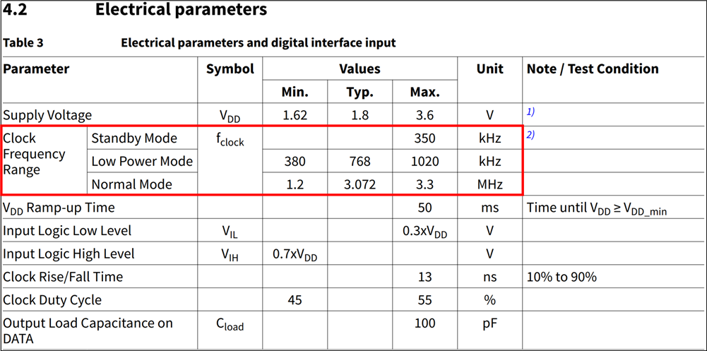
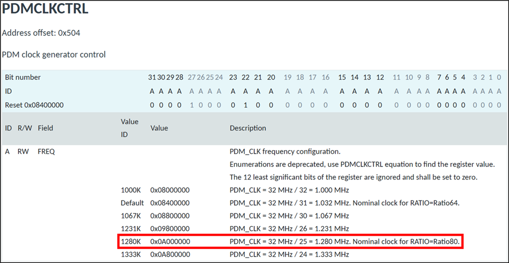
how do I adjust the PDM clock frequency to 1.28MHz, or how can I achieve this by changing the value of PDMCLKCTRL to 0x0A000000?

Below is my understanding after finding relevant documents. Please correct me if there are any errors, thank you.

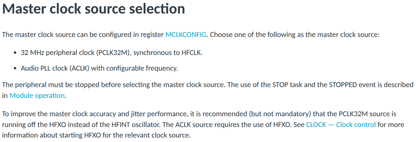
I saw the following explanation about PCLK32M and ACLK in the PDM Documentation.

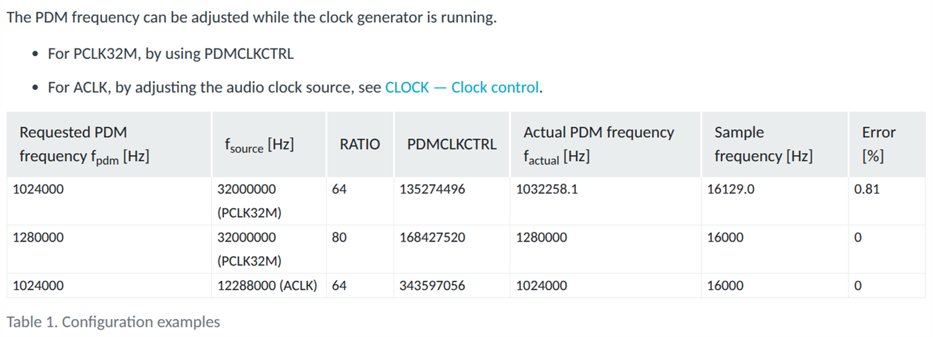
However, in the following overlay file of the DMIC sample, the clock source of &pdm0 is ACLK.

nrf5340dk_nrf5340_cpuapp.overlay (without any modifications)

&clock {
	hfclkaudio-frequency = <12288000>;
};

&pinctrl {
	pdm0_default_alt: pdm0_default_alt {
		group1 {
			psels = <NRF_PSEL(PDM_CLK, 0, 25)>,
				<NRF_PSEL(PDM_DIN, 0, 26)>;
		};
	};
};

dmic_dev: &pdm0 {
	status = "okay";
	pinctrl-0 = <&pdm0_default_alt>;
	pinctrl-names = "default";
	clock-source = "ACLK";
};

Based on the above explanation and overlay file, does this mean I cannot change the PDM clock frequency to 1.28MHz using PDMCLKCTRL? Or how can I achieve this by modifying the overlay's clock-source to PCLK32M and modifying the main code?

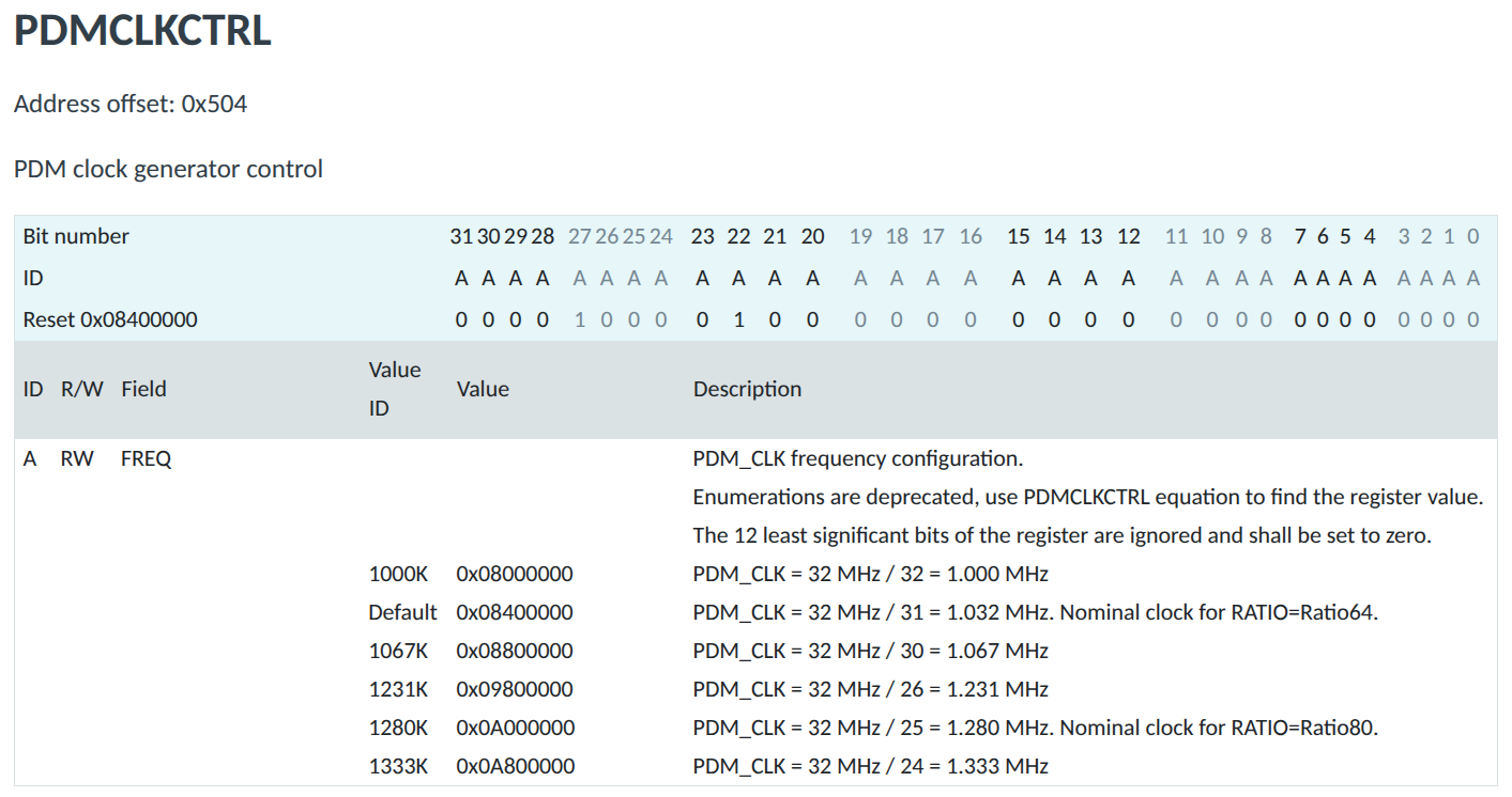
If not using PDMCLKCTRL, how can I achieve this by modifying the main code of the DMIC sample using ACLK?

main.c  (without any modifications)

#include <zephyr/kernel.h>
#include <zephyr/audio/dmic.h>

#include <zephyr/logging/log.h>
LOG_MODULE_REGISTER(dmic_sample);

#define MAX_SAMPLE_RATE  16000
#define SAMPLE_BIT_WIDTH 16
#define BYTES_PER_SAMPLE sizeof(int16_t)
/* Milliseconds to wait for a block to be read. */
#define READ_TIMEOUT     1000

/* Size of a block for 100 ms of audio data. */
#define BLOCK_SIZE(_sample_rate, _number_of_channels) \
	(BYTES_PER_SAMPLE * (_sample_rate / 10) * _number_of_channels)

/* Driver will allocate blocks from this slab to receive audio data into them.
 * Application, after getting a given block from the driver and processing its
 * data, needs to free that block.
 */
#define MAX_BLOCK_SIZE   BLOCK_SIZE(MAX_SAMPLE_RATE, 2)
#define BLOCK_COUNT      4
K_MEM_SLAB_DEFINE_STATIC(mem_slab, MAX_BLOCK_SIZE, BLOCK_COUNT, 4);

static int do_pdm_transfer(const struct device *dmic_dev,
			   struct dmic_cfg *cfg,
			   size_t block_count)
{
	int ret;

	LOG_INF("PCM output rate: %u, channels: %u",
		cfg->streams[0].pcm_rate, cfg->channel.req_num_chan);

	ret = dmic_configure(dmic_dev, cfg);
	if (ret < 0) {
		LOG_ERR("Failed to configure the driver: %d", ret);
		return ret;
	}

	ret = dmic_trigger(dmic_dev, DMIC_TRIGGER_START);
	if (ret < 0) {
		LOG_ERR("START trigger failed: %d", ret);
		return ret;
	}

	for (int i = 0; i < block_count; ++i) {
		void *buffer;
		uint32_t size;

		ret = dmic_read(dmic_dev, 0, &buffer, &size, READ_TIMEOUT);
		if (ret < 0) {
			LOG_ERR("%d - read failed: %d", i, ret);
			return ret;
		}

		LOG_INF("%d - got buffer %p of %u bytes", i, buffer, size);

		k_mem_slab_free(&mem_slab, buffer);
	}

	ret = dmic_trigger(dmic_dev, DMIC_TRIGGER_STOP);
	if (ret < 0) {
		LOG_ERR("STOP trigger failed: %d", ret);
		return ret;
	}

	return ret;
}

int main(void)
{
	const struct device *const dmic_dev = DEVICE_DT_GET(DT_NODELABEL(dmic_dev));
	int ret;

	LOG_INF("DMIC sample");

	if (!device_is_ready(dmic_dev)) {
		LOG_ERR("%s is not ready", dmic_dev->name);
		return 0;
	}

	struct pcm_stream_cfg stream = {
		.pcm_width = SAMPLE_BIT_WIDTH,
		.mem_slab  = &mem_slab,
	};
	struct dmic_cfg cfg = {
		.io = {
			/* These fields can be used to limit the PDM clock
			 * configurations that the driver is allowed to use
			 * to those supported by the microphone.
			 */
			.min_pdm_clk_freq = 1000000,
			.max_pdm_clk_freq = 3500000,
			.min_pdm_clk_dc   = 40,
			.max_pdm_clk_dc   = 60,
		},
		.streams = &stream,
		.channel = {
			.req_num_streams = 1,
		},
	};

	cfg.channel.req_num_chan = 1;
	cfg.channel.req_chan_map_lo =
		dmic_build_channel_map(0, 0, PDM_CHAN_LEFT);
	cfg.streams[0].pcm_rate = MAX_SAMPLE_RATE;
	cfg.streams[0].block_size =
		BLOCK_SIZE(cfg.streams[0].pcm_rate, cfg.channel.req_num_chan);

	ret = do_pdm_transfer(dmic_dev, &cfg, 2 * BLOCK_COUNT);
	if (ret < 0) {
		return 0;
	}

	cfg.channel.req_num_chan = 2;
	cfg.channel.req_chan_map_lo =
		dmic_build_channel_map(0, 0, PDM_CHAN_LEFT) |
		dmic_build_channel_map(1, 0, PDM_CHAN_RIGHT);
	cfg.streams[0].pcm_rate = MAX_SAMPLE_RATE;
	cfg.streams[0].block_size =
		BLOCK_SIZE(cfg.streams[0].pcm_rate, cfg.channel.req_num_chan);

	ret = do_pdm_transfer(dmic_dev, &cfg, 2 * BLOCK_COUNT);
	if (ret < 0) {
		return 0;
	}

	LOG_INF("Exiting");
	return 0;
}

Thank you very much!

Kevin

Parents Reply Children
  • Hi Håkon,


    Sorry, I'm not very familiar with PDM and my explanation may not be clear enough.


    My project uses the nRF5340 as the SoC, which connects to the Infineon IM69D128SV01 microphone via a PDM interface.

    Based on the clock frequency range specified in section 4.2 Electrical parameters of the IM69D128SV01 datasheet, the low-power mode range is between 380kHz and 1020kHz, and the normal mode range is between 1.2MHz and 3.3MHz.

    The nRF5340's PDM clock frequency range is between 1MHz and 1.333MHz. Therefore, based on the PDM clock frequency range limitation, I currently plan to adjust the PDM clock frequency to 1.28MHz to meet the microphone's normal mode frequency range for initial testing.

    IM69D128SV01 datasheet: https://www.infineon.com/assets/row/public/documents/24/49/infineon-im69d128s-datasheet-en.pdf?fileId=8ac78c8c85c5e5aa0185dfa527036dad


    nRF5340 datasheet: https://docs-be.nordicsemi.com/bundle/ps_nrf5340/page/nRF5340_PS_v1.6.pdf?_LANG=enus

    Based on my previous test following your suggested modifications, I found that the microphone couldn't record any sound (currently, I'm only testing with human voices).

    I suspect it's because I both set the minimum and maximum frequencies of the "cfg" variable to 1.28MHz, causing the microphone to only record sound at that frequency.

    However, this isn't the result I want. I want to be able to record real-life sounds (mostly human voices) with the PDM clock frequency at 1.28MHz.


    By the way, I found the APIs "nrf_pdm_clock_set()" and "nrf_pdm_ratio_set()" online. It's "possibly" possible to set the PDM clock frequency to 1.28MHz using "nrf_pdm_clock_set()" via "NRF_PDM_FREQ_1280K". I'm not sure about the purpose of "nrf_pdm_ratio_set()".

    However, I've tested this version, and it still can't record any sound. Is my modification correct and effective? If not, is there any way to achieve this through code?

    nrf5340_cpuapp_common.dtsi

    dmic: &pdm0 {
    	status = "okay";
    	pinctrl-0 = <&pdm0_default_alt>;
    	pinctrl-1 = <&pdm0_sleep>;
    	pinctrl-names = "default", "sleep";
    	clock-source = "PCLK32M";
    	queue-size = <192>;
    	zephyr,pm-device-runtime-auto;
    };
    
    // &clock {
    // 	hfclkaudio-frequency = <11288000>;
    // };

    dmic.c

    #define MAX_SAMPLE_RATE  16000
    #define SAMPLE_BIT_WIDTH 16
    #define BYTES_PER_SAMPLE sizeof(int16_t)
    /* Milliseconds to wait for a block to be read. */
    #define READ_TIMEOUT     110
    
    /* Size of a block for 50 ms of audio data. */
    #define BLOCK_SIZE(_sample_rate, _number_of_channels) \
    	(BYTES_PER_SAMPLE * (_sample_rate / 20) * _number_of_channels)
    
    /* Driver will allocate blocks from this slab to receive audio data into them.
     * Application, after getting a given block from the driver and processing its
     * data, needs to free that block.
     */
    #define MAX_BLOCK_SIZE   BLOCK_SIZE(MAX_SAMPLE_RATE, 1)
    
    static const struct device *const DMIC = DEVICE_DT_GET(DT_NODELABEL(dmic));
    
    int dmic_init(void)
    {
        int ret = -1;
        if (!device_is_ready(DMIC)) {
            LOG_ERR("%s is not ready", DMIC->name);
            return -1;
        }
    
        struct pcm_stream_cfg stream = { .pcm_width = SAMPLE_BIT_WIDTH,
                                         .mem_slab = &mem_slab,
                                         .block_size = MAX_BLOCK_SIZE,
                                         .pcm_rate = 16000 };
        struct dmic_cfg cfg = {
          .io =
              {
                  /* These fields can be used to limit the PDM clock
                   * configurations that the driver is allowed to use
                   * to those supported by the microphone.
                   */
                  .min_pdm_clk_freq = 450000,
                  .max_pdm_clk_freq = 3300000,
                  .min_pdm_clk_dc = 45,
                  .max_pdm_clk_dc = 55,
              },
          .streams = &stream,
          .channel =
              {
                  .req_num_streams = 1,
              },
      };
    
        cfg.channel.req_num_chan = 1;
        cfg.channel.req_chan_map_lo = dmic_build_channel_map(0, 0, PDM_CHAN_LEFT);
        cfg.streams[0].pcm_rate = MAX_SAMPLE_RATE;
        cfg.streams[0].block_size =
            BLOCK_SIZE(cfg.streams[0].pcm_rate, cfg.channel.req_num_chan);
    
        LOG_INF(
            "PCM output rate: %u, channels: %u",
            cfg.streams[0].pcm_rate,
            cfg.channel.req_num_chan);
    
        ret = dmic_configure(DMIC, &cfg);
        if (ret < 0) {
            LOG_ERR("Failed to configure the driver: %d", ret);
        }
    
        /* Force PDMCLKCTRL to 1280K => 1.280 MHz */
        nrf_pdm_clock_set(NRF_PDM0, NRF_PDM_FREQ_1280K);
    
        /* Optional: choose RATIO=80 to get 16 kHz from 1.28 MHz */
        nrf_pdm_ratio_set(NRF_PDM0, NRF_PDM_RATIO_80X);
    
        nrf_pdm_gain_set(NRF_PDM0, NRF_PDM_GAIN_MAXIMUM, NRF_PDM_GAIN_MAXIMUM);
        nrf_pdm_gain_t l_gain = 0;
        nrf_pdm_gain_t r_gain = 0;
        nrf_pdm_gain_get(NRF_PDM0, &l_gain, &r_gain);
    
        LOG_INF(
            " nrfx_clock_hfclkaudio_config_get = %d",
            nrfx_clock_hfclkaudio_config_get());
        LOG_INF("PDM gain = %d", l_gain);
        return 0;
    }

    Thank you very much for your explanation and help.


    Best regards,

    Kevin

  • Hi Kevin,


    My apologies for the late reply. I have been out of the office.

    Kevin Lin said:

    The nRF5340's PDM clock frequency range is between 1MHz and 1.333MHz. Therefore, based on the PDM clock frequency range limitation, I currently plan to adjust the PDM clock frequency to 1.28MHz to meet the microphone's normal mode frequency range for initial testing.

    This sounds reasonable.

    Kevin Lin said:
    Based on my previous test following your suggested modifications, I found that the microphone couldn't record any sound (currently, I'm only testing with human voices).

    Was there any errors or issues reported over the console?

    Did you check if there was any output on the GPIOs that you chose?


    It a bit unclear to me if everything worked as expected when you had a wider frequency range set. Could you clarify this?


    Kind regards,

    Håkon

  • Hi Håkon,

    Sincere apologies for the delayed response. I no longer need this at this stage. Thank you for your help.

    Best regards,

    Kevin

  • Hi Kevin,


    Nothing to apologise for. Please feel free to contact us if anything else should pop up.

    I wish you a great day!


    Kind regards,

    Håkon

  • Hi Håkon,

    No problem at all. Thank you, and have a great day as well!

    Best regards,

    Kevin

Related