If you have tested the nRF9151's GPS with the CMW100 or IQ station. We need to know:
1. What test waveform file is required?
2. Should we use the ARB file or the CW waveform?
If you have tested the nRF9151's GPS with the CMW100 or IQ station. We need to know:
1. What test waveform file is required?
2. Should we use the ARB file or the CW waveform?
Hi,
For full GNSS signaling CN0 test, you may use a GNSS ARB signal from a signal generator (conducted GNSS signaling mode, typically around -135 dBm), and read CN0 from the GNSS logs / UART traces as described in the documentation. And as in this case you requires a GNSS‑modulated signal, the testing should be done using an ARB GNSS waveform or a GNSS simulator rather than a CW tone.
Best Regards,
Syed Maysum

Hi,
Any recommended ARB files for GPS testing with the CMW100/CMW500?
Hi,
I previously tried using the GPS_single.wv or GPS_default.wv waveform files on the CMW100 or CMW500 for conducted GPS L1 testing, but the CN0 values kept fluctuating, jumping between the original 40 and 0.
Hi,
CN0 intermittently dropping to 0 during conducted GNSS signaling tests typically indicates that the receiver temporarily loses tracking and then reacquires the signal. This is most often related to signal level or test setup calibration, rather than the ARB waveform itself. Please verify that the effective signal level at the nRF9151 GNSS input (including cable loss and any external LNA gain) is very low, typically around -135 dBm, and allow sufficient time for the receiver to reach stable tracking.
Additionally, please check the modem firmware version. With modem firmware v2.0.1, there is a known behavior where tracked satellite reporting can fluctuate after initial acquisition. Updating to modem firmware v2.0.2 or later is recommended, as it includes improvements to GNSS tracking stability and reporting.
Best Regards,
Syed Maysum
Hi,
Sorry for the late reply. For the NRF9151 test, the firmware version used was nrf91x1_2.0.2. The signal level generated by the test instrument was set to -130 dBm. Additionally, the external LNA for the GNSS has a gain of 16 dB. A 50Ω cable was used to connect to the test port, with a 1 dB compensation for line loss. However, during testing, the CN0 value still exhibited fluctuations/jumping. Attached is the log file of the CN0 test results.
Hi,
No problem, thanks for sharing the setup details. Based on the numbers you provided, the effective signal level at the nRF9151 GNSS input comes out to around –115 dBm (–130 dBm generator + 16 dB LNA – 1 dB cable loss). This is quite a bit stronger than what a GNSS receiver normally expects.
For conducted GNSS signaling CN0 tests, the recommended level at the GNSS input is typically around –135 dBm, and this already assumes that an external GNSS LNA is present. If the signal is much stronger than this, the receiver can temporarily lose tracking, which would show up as CN0 fluctuations. We suggest lowering the effective signal level at the GNSS input (for example by reducing the generator output, or temporarily bypassing the external LNA) so that it is closer to –135 dBm, and then re-running the test.
Best Regards,
Syed Maysum
Hi,
I don't think dBm and dB can be converted equivalently — their units are different. The actual power reaching the IC is still –130 dBm.
Hi,
I don't think dBm and dB can be converted equivalently — their units are different. The actual power reaching the IC is still –130 dBm.
Hi,
You’re right that dBm and dB are different units. In practice, dBm is the absolute signal level, while dB represents gain or loss in the signal path, and they are combined to determine the power seen at the IC input.
Could you please try lowering the signal generator output to around -150 dBm while keeping the same external LNA enabled, so that the effective level at the GNSS input is closer to -135 dBm, and then re-run the test? This would help us confirm whether the signal level is the cause of the CN0 fluctuations.
Best Regards,
Syed Maysum
Hi,
I tested by setting the instrument output power to -130 dBm, with the external LNA turned on and an attenuator added, adjusting the output power to -150 dBm. However, the CN0 value remains very low, reaching a maximum of only 25, and it still fluctuates, sometimes dropping to 0.
Hi,
Thanks for your response. Your case is being discussed internally by relevant team and will be responded very soon.
Best Regards,
Syed Maysum
Hi,
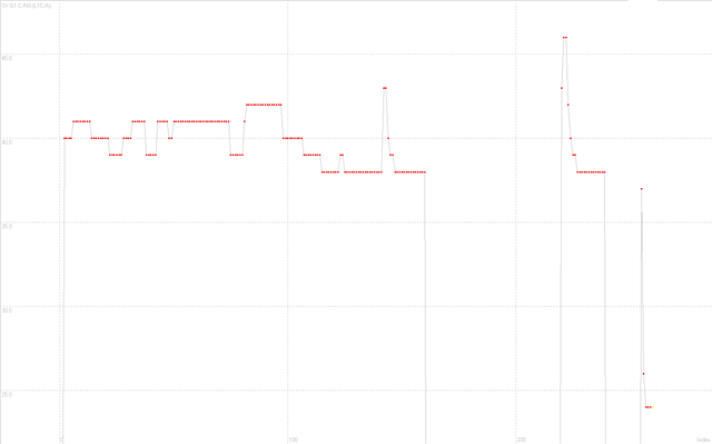
Thank you for the additional details. Based on our internal review of the test results, the observed behavior is consistent with the characteristics of the GNSS ARB waveform. The example ARB files typically contain a single GPS signal. At -130 dBm, the nRF9151 correctly tracks SV1 with CN0 around 38-42 dB-Hz, which is expected and indicates normal GNSS operation.
The tracking loss after ~2 minutes likely coincides with the rapid adjustment of the signal level to -150 dBm. Sudden power changes during tracking can cause temporary loss of lock. The signal is later reacquired with CN0 again above ~38 dBHz, confirming proper receiver behavior when the signal level is stable.
The additional fluctuating CN0 values (0-25 dBHz) correspond to acquisition attempts for other satellites rather than stable tracked signals. With ARB playback, these acquisition artifacts can be more visible, especially if there is some noise in the waveform or reflections in the conducted RF setup. In controlled GNSS simulator configurations generating a single GPS signal (like in single channel simulator mode), this effect is typically less pronounced.
We recommend keeping the signal level stable during measurement and ensuring the RF path is clean.
Best Regards,
Syed Maysum