RSSI on Fanstel module with FEM dropped after SDK upgrade

Hi!


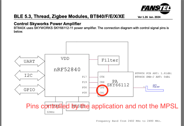
I just upgraded a product we developed using a Fanstel BT840X module (nrf52840 with a Skyworks SKY66112 amplifier) from SDK 2.3.0 to SDK 3.1.1 and I noticed that our radio signal quality has dropped enough that there's clearly some problem.


I am using the 802.15.4 hardware at a low level to send and receive packets from our gateway device to wireless devices which are currently still running the older SDK 2.3 code. I use nrf_802154_tx_power_set(22) to set the power level, nrf_802154_transmit_raw() to send, and nrf_802154_received_raw() to receive.


I can see the a graph of our link quality indicator values so I can see that it gets worse as I go back and forth between the new and old firmware. Our LQI has been scaled to be a 0-100% value with 0 being a terrible signal and 100% being a great signal. Before the upgrade, one particular device I talk to was steadily reporting a LQI if around 80, and after the upgrade it's around 50. So it's still working some, just not as well as it was.

One of the things I had to change in the upgrade was to set CONFIG_NRF_802154_TEMPERATURE_UPDATE=n because I get a kernel panic before reaching main without it - don't know if that's a clue.

I've attached my prj.conf and the dts file for my custom board.

Can you find anything I'm doing wrong that would explain the signal quality change with the SDK upgrade? Maybe there's a new CONFIG_ item that I need to find and turn on or a different way to use the 802.15.4 API to correctly set the output power?

Thanks!

Glen

customer_gateway_fanstel.dts8484.prj.conf

Parents Reply
  • Yes I think I have those configured correctly with the following code that's called at powerup:

    #define SKYWORKS_AMPLIFIER_CTX_PIN 17 // GPIO port 0
    #define SKYWORKS_AMPLIFIER_CRX_PIN 19 // GPIO port 0
    #define SKYWORKS_AMPLIFIER_CPS_PIN 6 // GPIO port 0
    #define SKYWORKS_AMPLIFIER_CHL_PIN 8 // GPIO port 0

    m_gpio_port_0 = (struct device *)(device_get_binding("GPIO_0"));
    m_gpio_port_1 = (struct device *)(device_get_binding("GPIO_1"));

    gpio_pin_configure(m_gpio_port_0, SKYWORKS_AMPLIFIER_CPS_PIN, GPIO_OUTPUT_INACTIVE); // GPIO_OUTPUT_INACTIVE Configures GPIO pin as output and initializes it to a logic 0.
    gpio_pin_configure(m_gpio_port_0, SKYWORKS_AMPLIFIER_CHL_PIN, GPIO_OUTPUT_ACTIVE); // GPIO_OUTPUT_ACTIVE Configures GPIO pin as output and initializes it to a logic 1.

Children
  • Yes, your pin configuration appears to be correct. Ideally, it would be good if you could measure the CHL and CPS signals to confirm they are being driven to ‘1’ and ‘0’ respectively, but I realise the pads may be difficult to access. Alternatively, you could use the peripheral viewer in VS Code (or a similar tool) to read the GPIO configuration registers to confirm the setup, and also check the serial peripheral interfaces to ensure that none are configured to use the same pins.

  • I ended up digging down into the library to find the function where the "power" RSSI value is set and it looks like it's just a numerical difference (as opposed to a real signal level difference). The older version of the SDK did not account for the LNA gain in the reported number and the new version does in nrf_802154_trx_rssi_last_sample_get().

    So I ended up just updating my dts file to tell it that there's no gain from the LNA because I want consistency of behavior:

    nrf_radio_fem: skyFem {
    compatible = "skyworks,sky66112-11", "generic-fem-two-ctrl-pins";
    ctx-gpios = <&gpio0 17 GPIO_ACTIVE_HIGH>;
    crx-gpios = <&gpio0 19 GPIO_ACTIVE_HIGH>;
    ctx-settle-time-us = <23>;
    crx-settle-time-us = <5>;
    tx-gain-db = <22>;
    rx-gain-db = <0>; /* The real gain is 11dB but this number is included in the reported RSSI value and it has not been in the past so including it now is a change we dont want */
    };

Related