nrf9151 minimal wiring

Clarify the minimum mandatory external connections and pin/rail requirements for an nRF9151 to boot and run a flashed application, and determine why serial_lte_modem (SLM) shows no UART response on an external bare module wired directly to pads after successful SWD programming. Also confirm whether using 3.3 V on both VDD and VDD_GPIO is supported.

Reference (works)

  • Board: nRF9151-DK
  • Application: serial_lte_modem (SLM) from NCS
  • Behavior: UART responds as expected (AT interface)

Failing target (external / wired pads)

  • Hardware: external nRF9151 module/chip only; wires soldered directly to pads
  • Behavior: after flashing SLM, no UART banner/AT response

Programming status (confirmed)

  • The external module can be programmed via SWD successfully.
  • nRF Connect / Programmer confirms the image was written correctly (flash operation completes without errors).
  • The behavior diverges after flashing: DK runs and responds; external target is silent on UART.
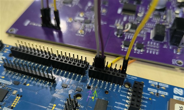
Connections used

  • SWD programming wiring
    • VDD = 5 V
    • GND
    • SWDIO
    • SWDCLK
    • nRESET
  • Runtime wiring for UART test (direct power)
    • VDD = 5 V
    • GND
    • VDD_GPIO = 1.8 V
    • ENABLE = HIGH
    • P0.26 = TX
    • P0.27 = RX

Additional test using the nRF9151-DK as a power/UART host (still fails)

  • The external module was connected to the nRF9151-DK.
  • The DK’s onboard modem TX/RX path was opened/disconnected to isolate the DK’s modem and reroute the DK UART TX/RX to the external module instead.
  • The external module was powered using the DK native rails (5 V / 1.8 V) and tested through the DK’s UART interface.
  • Result: SLM still does not respond on UART.

Requested from Nordic

  • Definitive list of mandatory rails/pins/conditions (and sequencing) required for nRF9151 to:
    • boot and execute a flashed application reliably
    • expose UART for SLM
  • Confirmation whether it is supported to power a design with:
    • VDD = 3.3 V and VDD_GPIO = 3.3 V
    • any restrictions, required configuration, or unsupported conditions
  • Root-cause guidance for “flash verified but UART silent” on custom/bare hardware, including:
    • SLM default UART instance and pin mapping differences between DK and custom target
    • required devicetree/Kconfig changes to bind SLM UART to P0.26/P0.27
    • reset/ENABLE handling and required pulls that can prevent the app from running or keep UART inactive
    • any mandatory external circuitry/rails provided by the DK that are missing in a bare module wiring
Parents
  • Hi,

    Programming the nRF9151 over SWD only confirms that the image was written to flash; it does not guarantee that the device is actually booting and running the SLM application. In your setup, there are a few common reasons why the UART can appear completely silent even when flashing succeeds.

    1. First, the Serial Modem application does not use P0.26/P0.27 by default. On the nRF9151 DK, SLM uses UART2 on P0.10 (TX) and P0.11 (RX) for an external host, so unless a devicetree overlay is added to remap the UART, any output will be on those default pins.
    2. Second, SLM uses DTR-based UART power management: if DTR (P0.31, active low) is not asserted, the UART is kept powered down, which results in no AT banner or response even if the application is running.
    3. Third, the UART signal levels are defined by VDD_GPIO, so if VDD_GPIO is 1.8 V while the UART host operates at 3.3 V, the signals may not be detected correctly.
    4. And for nRF9151, VDD = 3.0 to 5.5 V and VDD_GPIO = 1.7 to 3.6 V are allowed, so using 3.3 V on both is within spec, with the constraints that VDD must be applied before VDD_GPIO, VDD_GPIO should be low when ENABLE is low, and VDD_GPIO should be removed before VDD.

    So initially we recommend powering VDD and VDD_GPIO at 3.3 V, ensuring ENABLE is driven correctly, asserting DTR (or disabling DTR-based UART power management), and either wiring to the default SLM UART pins or remapping the UART to your chosen pins via a devicetree overlay.

    Best Regards,
    Syed Maysum

  • Thank you Syed for the quick response,

    1. We are using the "nrf9151dk_serial_lte_modem_2025-08-14_6c6e5b32.hex" file on both configurations. Using the DK, the pins containing the UART are P0.27/P0.26, verified as we used a version of our board with pins for RX, TX, GND and 3V3, connecting RX, TX and GND with the powered DK we have a communication with P0.27/P0.26.
     
    2. I will test the DTR pin.
    3. In DK, the VDD_GPIO is 1.8V and we have communication.
    4. Thank you for reassuring this aspect, we will have the boot sequence in mind.

    I will be testing the uart2 pins and modifying the devicetree and compiling the project.

    Thank you again for the help.
    Best Regards and a happy 2026,
    Paulo Scarello

  • Hi,

    Thanks for the update. Please let us know the results after testing.

    Best Regards,
    Syed Maysum

Reply Children
  • Hi Syed,

    Pulling the P0.31 LOW returned no difference, but as I was measuring the pins I came across the P0.29 and P0.28 pins as HIGH.

    This led me to compile the SERIAL_LTE_MODEM sample from nRF SDK v3.1.1 as is and it showed me the devicetree:

    It shows that the uart0 is indeed P0.27/P0.26 (TX/RX) and uart1 as P0.29/P0.28 (TX/RX), there is no mention to a DTR (not that I found), the P0.31 is used as SCL for i2c2.

    Now,

    Is there any reference for implementing the SLM in custom hardware?

    Any other suggestion that you can think of?


    Best Regards,
    Paulo Scarello

  • Update,

    Using the DK and setting P0.15 (CTS) to LOW, the module output the following message:

    All pins have been configured as non-secure
    [00][1B][1;34mBooting TF-M v2.1.1-ncs4[1B][0m
    [00][1B][1;34m[Sec Thread] Secure image initializing![1B][0m
    [00]TF-M isolation level is: [00]0x00000001
    TF-M Float ABI: Hard
    [00]Lazy stacking enabled
    [00]

    But at the moment, the module do not receive any data from nRF5340 that i send through Termite.

    I will be making more tests.

    Best Regards,
    Paulo Scarello

  • Hi,

    Thank you for the detailed testing and updates, Seeing the output: Booting TF-M v2.1.1-ncs4 confirms that the nRF9151 on your custom hardware is powered correctly, released from reset, and executing the flashed firmware. This rules out issues related to flashing, ENABLE, reset, or the main power rails. The remaining behavior is explained by the UART configuration used by the Serial LTE Modem (SLM) application. By default, SLM enables hardware flow control (RTS/CTS). On the nRF9151 DK these signals are handled automatically by the onboard circuitry, but on custom or bare hardware they must be explicitly driven.

    Your observation that pulling CTS (P0.15) LOW causes UART output to appear confirms that hardware flow control is active. At this point, UART TX is working, but UART RX will remain blocked unless RTS/CTS are handled correctly. You can try out one of the following approaches:

    1. Hardware option:
      1. Connect and use all UART flow-control signals (TX, RX, RTS, CTS).
      2. For testing, CTS can be held LOW and RTS connected to the host’s CTS input.
    2. Software option
      1. Rebuild the SLM application with hardware flow control disabled (e.g. disable CONFIG_UART_0_NRF_HW_FC for the UART instance in use), allowing a simple 2-wire UART (TX/RX/GND).

    Best Regards,
    Syed Maysum

  • Thank you for the clarification and guidance.

    The issue is confirmed resolved by disabling hardware flow control in the SLM build. With RTS/CTS disabled, the UART operates correctly over a simple 2-wire interface (TX/RX/GND) on the custom hardware. This fully explains the previously silent UART behavior and confirms that power, reset, and boot sequencing were correct.

    Appreciate the detailed explanation regarding SLM’s default UART flow-control behavior and the difference between DK handling and bare hardware.

    Best regards,
    Paulo Scarello

Related