How to config the tdm port on nrf54lm20

I want to try the tdm function on the nrf54lm20 dk.

But i have encountered problem in the first step.

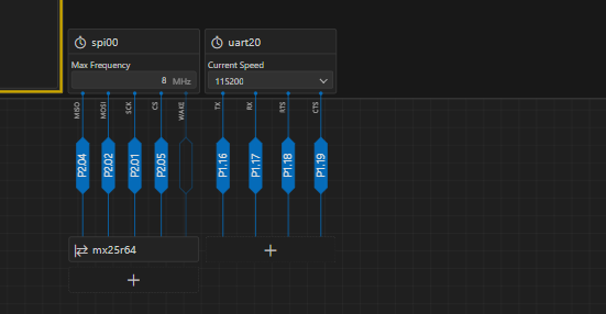
I do not know how to add the tdm port and assign the pin.

Whin i enable the tdm in the device tree, there is nothin in this page.

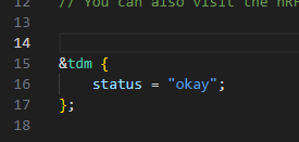
only this code generated in the overlay files

I try to assign the pin:

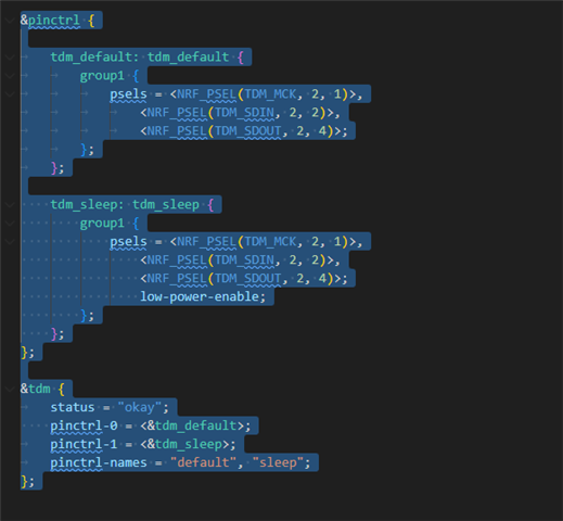
But seems invalid...

Can you help me to pass the first step?

Thank you very much!

Parents
  • Hi,


    The TDM can be sourced via two clocks, as shown here:

    https://docs.nordicsemi.com/bundle/ps_nrf54LM20A/page/tdm.html#d1594e1438


    44100 Hz is not exactly possible with these two clock sources, so you will have a bit of a miss, but 210 Hz off is a bit much.

    I see that the example that I sent you is missing a crucial component, and that is starting the HFXO.


    Could you try adding this function (and calling it) on boot?

    https://github.com/nrfconnect/sdk-nrf/blob/main/samples/peripheral/radio_test/src/main.c#L28-L70


    Similar to this (headers and all added for you):

    /*
     * Copyright (c) 2012-2014 Wind River Systems, Inc.
     *
     * SPDX-License-Identifier: Apache-2.0
     */
    
    #include <zephyr/kernel.h>
    #include <zephyr/device.h>
    #include <zephyr/drivers/i2s.h>
    #include <zephyr/sys/iterable_sections.h>
    #include <zephyr/drivers/clock_control.h>
    #include <zephyr/drivers/clock_control/nrf_clock_control.h>
    #if NRF54L_ERRATA_20_PRESENT
    #include <hal/nrf_power.h>
    #endif /* NRF54L_ERRATA_20_PRESENT */
    
    #include <zephyr/logging/log.h>
    
    #define LOG_MODULE_NAME i2s_test
    LOG_MODULE_REGISTER(LOG_MODULE_NAME);
    
    #define SAMPLE_NO 64
    #define NUM_BLOCKS 4
    #define BLOCK_SIZE (SAMPLE_NO * sizeof(int16_t))
    
    K_MEM_SLAB_DEFINE(tx_mem_slab, BLOCK_SIZE, NUM_BLOCKS, 4);
    
    const struct device *const i2s_dev = DEVICE_DT_GET(DT_ALIAS(i2s_node0));
    
    /* Audio samples*/
    static int16_t data[SAMPLE_NO];
    
    static void clock_init(void)
    {
    	int err;
    	int res;
    	struct onoff_manager *clk_mgr;
    	struct onoff_client clk_cli;
    
    	clk_mgr = z_nrf_clock_control_get_onoff(CLOCK_CONTROL_NRF_SUBSYS_HF);
    	if (!clk_mgr) {
    		printk("Unable to get the Clock manager\n");
    		return;
    	}
    
    	sys_notify_init_spinwait(&clk_cli.notify);
    
    	err = onoff_request(clk_mgr, &clk_cli);
    	if (err < 0) {
    		printk("Clock request failed: %d\n", err);
    		return;
    	}
    
    	do {
    		err = sys_notify_fetch_result(&clk_cli.notify, &res);
    		if (!err && res) {
    			printk("Clock could not be started: %d\n", res);
    			return;
    		}
    	} while (err);
    
    #if NRF54L_ERRATA_20_PRESENT
    	if (nrf54l_errata_20()) {
    		nrf_power_task_trigger(NRF_POWER, NRF_POWER_TASK_CONSTLAT);
    	}
    #endif /* NRF54L_ERRATA_20_PRESENT */
    
    #if defined(NRF54LM20A_ENGA_XXAA)
    	/* MLTPAN-39 */
    	nrf_clock_task_trigger(NRF_CLOCK, NRF_CLOCK_TASK_PLLSTART);
    #endif /* defined(NRF54LM20A_ENGA_XXAA) */
    
    	printk("Clock has started\n");
    }
    
    static int configure_stream(const struct device *dev_i2s, uint32_t frame_clk_freq)
    {
    	int err;
    	struct i2s_config i2s_cfg;
    
    	i2s_cfg.word_size = 16U;
    	i2s_cfg.channels = 1U;
    	i2s_cfg.format = I2S_FMT_DATA_FORMAT_I2S;
    	i2s_cfg.frame_clk_freq = frame_clk_freq;
    	i2s_cfg.block_size = BLOCK_SIZE;
    	i2s_cfg.timeout = 1000;
    	i2s_cfg.options = I2S_OPT_FRAME_CLK_SLAVE | I2S_OPT_BIT_CLK_SLAVE;
    
    	i2s_cfg.mem_slab = &tx_mem_slab;
    	err = i2s_configure(dev_i2s, I2S_DIR_TX, &i2s_cfg);
    	if (err < 0) {
    		LOG_ERR("Failed to configure I2S TX stream (%d)\n",
    			 err);
    		return err;
    	}
    
    	return 0;
    }
    
    static void fill_buf(int16_t *tx_block)
    {
    	memcpy(tx_block, data, sizeof(data));
    }
    
    int main(void)
    {
    	int err;
    	int tx_idx;
    	void *tx_block[NUM_BLOCKS];
    	clock_init();
    	LOG_INF("I2S Sample started");
    	/* Fill with a fixed reckognizable pattern to make
    	   any gaps apparent */
    	memset(data, 0xAA, sizeof(data));
    
        if (!device_is_ready(i2s_dev)) {
    		LOG_ERR("Device %s is not ready.", i2s_dev->name);
    		return -EIO;
    	}
    
    	err = configure_stream(i2s_dev, 44100);
    	if(err) {
    		LOG_ERR("configure_stream() failed. (err %d)", err);
    	}
    
    	/* Prepare TX data blocks */
    	for (tx_idx = 0; tx_idx < NUM_BLOCKS; tx_idx++) {
    		err = k_mem_slab_alloc(&tx_mem_slab, &tx_block[tx_idx],
    				       K_FOREVER);
    		if(err) {
    			LOG_ERR("k_mem_slab_alloc() failed. (err %d)", err);
    		}
    		fill_buf(tx_block[tx_idx]);
    	}
    
    	tx_idx = 0;
    
    	/* Prefill TX queue */
    	err = i2s_write(i2s_dev, tx_block[tx_idx++], BLOCK_SIZE);
    	if(err) {
    		LOG_ERR("i2s write() failed. (err %d)", err);
    	}
    
    	err = i2s_write(i2s_dev, tx_block[tx_idx++], BLOCK_SIZE);
    	if(err) {
    		LOG_ERR("i2s write() failed. (err %d)", err);
    	}
    
    	i2s_trigger(i2s_dev, I2S_DIR_TX, I2S_TRIGGER_START);
    
    	/* Keep alternating between the two buffers */
    	for(;;) {
    		
    		tx_idx = tx_idx & (NUM_BLOCKS-1);	
    		err = i2s_write(i2s_dev, tx_block[tx_idx], BLOCK_SIZE);
    		if(err) {
    			LOG_ERR("i2s write() failed. (err %d)", err);
    			return 1;
    		}
    
    		err = k_mem_slab_alloc(&tx_mem_slab, &tx_block[tx_idx],
    				       K_FOREVER);
    		if(err) {
    			LOG_ERR("k_mem_slab_alloc() failed. (err %d)", err);
    		}
    		fill_buf(tx_block[tx_idx]);
    		tx_idx++;
    	}
    
    	return 0;
    }


    Kind regards,

    Håkon

  • Hello Håkon

    Thank you for your help.

    I followed your advice and tried your code, add the clock_init.

    But seem that the clock is worse...

    44.1K

    48K

    Do you have any suggestions for this?

    Thank you very much!

  • Hello Håkon

    No worries, you've already helped me a lot and thanks for that.

    And thanks for your detailed explanation, which has been truly beneficial to me.

    However, if you switch to the 24 MHz clock source, you will be much closer to the wanted 44.1 kHz:

    24000 / 44.1 = 17.007 (44.13 kHz)

    I have read the page you shared to me and the datasheet of nRF54LM20A, if i change the "

    mck-clock-source" to ACLK, seems it is the 24M? Do I understand correctly?
    The caveat at this time is that the zephyr driver does not support this clock source yet for the nRF54LM20, which I will report internally.

    Or you mean that now i can not use ACLK as “mck-clock-source”?

    There is still another question that confuses me, now we use I2S for TDM, does this mean that we cannot really use TDM format signals, for example, I don't think setting "i2s_cfg.channels" to a value greater than 2 is valid...

    Thank you very much!

  • Hello,


    huma said:

    I have read the page you shared to me and the datasheet of nRF54LM20A, if i change the "

    mck-clock-source" to ACLK, seems it is the 24M? Do I understand correctly?

    Yes, this shall change the clock source for MCK output, but I would recommend that you double-check the SCK/WS output to ensure that those are correct.

    As mentioned, the driver is not fully supporting these features, it seems.

    huma said:
    There is still another question that confuses me, now we use I2S for TDM, does this mean that we cannot really use TDM format signals, for example, I don't think setting "i2s_cfg.channels" to a value greater than 2 is valid...

    These two modes are not setting max_num_of_channels=2:

    https://github.com/nrfconnect/sdk-zephyr/blob/main/drivers/i2s/i2s_nrf_tdm.c#L533-L546


    ie. "I2S_FMT_DATA_FORMAT_PCM_SHORT" and "I2S_FMT_DATA_FORMAT_PCM_LONG".

    This test sets up different modes and configurations, which could be beneficial for your use-case:

    https://github.com/nrfconnect/sdk-zephyr/blob/main/tests/drivers/i2s/i2s_additional/src/main.c


    Kind regards,

    Håkon

  • Hello Håkon

    Thank you, i have to ask for help...

    I modified your project, the wave(lrclk, bclk, data) looks good, but when i connect to a ex-codec(adau1761),  the sound is distortion(can distinguish sound, but with heavy distortion, like data misalignment). But the same voice data i played on nrf5340 audio DK is well.

    And i have tried everything i can, but i can not find the problem, can you help me?

    hello_world_i2s_lm20a_modified.zip

    Thank you very much!

  • Hello,


    huma said:
    I modified your project, the wave(lrclk, bclk, data) looks good, but when i connect to a ex-codec(adau1761),  the sound is distortion(can distinguish sound, but with heavy distortion, like data misalignment). But the same voice data i played on nrf5340 audio DK is well.

    It hard for me to give a good indication, as I do not have the same setup as you.

    How does the waveforms (logic trace) compare between the two setups? Is the working communication I2S or left/right justified?


    Kind regards,

    Håkon

  • Hello Håkon

    I understand, you have already help me a lot.

    Thank you very much!

    I will close this ticket.

Reply Children
No Data
Related