nRF9151 Low Power Mode.

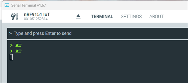
I am using the nRF9151 DK, using the Serial LTE Modem firmware from the nRF Connect quick start.

I am planning to use nRF9151 as a serial modem, and connect it to my Host MCU using UART.

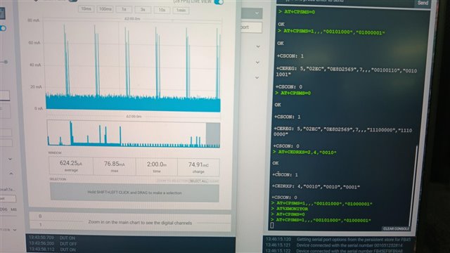
I am using the Power Profile II to measure the current of VDD_nRF.

Questions:

  1. Is this the product code that I should be using for my final product?
  2. Power save mode:
    1. I set the modem LPM. The average current is about 500uA in LPM. Why is it still so high? What is nRF9151 drawing current for? Is it because nRF9151 UART is still enabled?
    2. I press button 1 on the DK, the average current went down to 3uA.
    3. I press button 1 again, it seems to wake the nRF9151 up, with average current about 500uA again, but I lost all network configurations.
    4. Questions:
      1. What does button 1 do exactly? Any documents that describe exactly what it does?
      2. What is the proper way to go into deep power save mode, assuming I am using this Serial LTE Modem firmware in my final product?
      3. Is there a even lower power mode that the button 1 method? i.e. average current < 1uA maybe?
  3. There are some instances, when I leave the DK alone for maybe 10 mins, then I tried to send a AT command, the DK is not responsive in the sense it did not send back "OK" or network messages. However, my AT command was executed (based on the current profile of the Power Profiler II). Is this a know issue? Below image shows this error. In the image, bottom right, a few AT commands are sent but there were not response received.

Parents
  • Hi,

    Is this the product code that I should be using for my final product?

    I'm not sure to understand what you are asking here... If you are asking if the serial modem add-on (previously called "Serial LTE Modem (SLM)") is the right firmware to flash on the nRF9151 if you want to use as a modem-only solution; yes it is. However, if you want to use it with a host MCU, you probably want to use the devicetree overlay "overlay-external-mcu.overlay" file.

    What does button 1 do exactly? Any documents that describe exactly what it does?

    The button is connected to the UART DTR pin. All the documentation about the UART is here.

    What is the proper way to go into deep power save mode, assuming I am using this Serial LTE Modem firmware in my final product?

    All our normal power saving techniques (link) still applies for the Serial Modem add-on.

    I don't know how relevant it is but the nRF9151 is not only a modem, it has an application MCU. If the embedded MCU of the nRF9151 is enough for your needs you don't need a host MCU which can help you save power.

    Is there a even lower power mode that the button 1 method? i.e. average current < 1uA maybe?

    There are the "System OFF" and "System Disabled" mode, but it greatly depends on your application, as with "System OFF", the core system functionality is powered down and ongoing tasks terminated, and only the reset and the wake-up functions are available and responsive. And with "System Disabled" the chip is basically fully shut down. You can find the documentation about these modes here.

    There are some instances, when I leave the DK alone for maybe 10 mins, then I tried to send a AT command, the DK is not responsive in the sense it did not send back "OK" or network messages. However, my AT command was executed (based on the current profile of the Power Profiler II). Is this a know issue? Below image shows this error. In the image, bottom right, a few AT commands are sent but there were not response received.

    This is not an issue that I know of. I wasn't able to replicate it. Can you please document what you did a bit better so that I can try to replicate it?

    Best regards,

    Simon D-M

  • Hi Simon,

    Thanks for your reply.

    I have a external host MCU that will communicate with nRF9151 using AT commands. I want to use nRF9151 as a Serial LTE Modem. Meaning I do not want to modify any of the firmware (application and modem). I will just program whatever production-certified modem firmware and application firmware without any recompilation, which means I won't need to use overlay-external-mcu.overlay. Is this possible?

    I am able to get the modem to PSM but the current is not low enough as the application MCU is still operating. Based on my use case, I won't be able to modify any nRF9151 internal registers directly, unless it is accessible through AT commands. Are there AT commands that set nRF9151 to deep sleep? I understand I can wake it up from deep sleep using some GPIOs. Which GPIOs have the wake up function besides the DTR pin and Enable pin?

    Also I need your advise on the power saving. If my device only transmit once a day, will setting the nRF9151 to deep sleep be more power efficiency, or disabling it using the ENABLE pin be better? I am not sure what is the overhead and the extra current required to initialize nRF9151 when I toggle the ENABLE pin to wake it up.

    For the error, let me try to record the steps to reproduce it and post it here.

    Thanks,

    Alex.

  • Hi Alex,

    Medical Device said:
    Is this hex file the same one used in nRF Connect Desktop, Serial Modem? i.e. Is the one used in the quick start in nRF Connect Desktop, serial modem, compiled with "overlay-external-mcu.overlay"?

    No, the one flashed by the "Quick Start" application from nRF Connect for Desktop is not compiled with the overlay. It may also be a few versions older than the one on the GitHub.

    Medical Device said:
    Is this hex file for the application MCU only? Or does it also includes the modem firmware/stack? Do I need a separate hex file, i.e. 1 for application MCU and another for modex?

    In our nRF91 chips, we have 2 cores: The Application core, which contains the Serial Modem add-on in your case. And a modem core which contains the modem firmware. They are both programmable independently.

    The .hex you download are only for the application core. If you want to update the modem core, you can follow this guide. You can also download the modem firmware on the nRF9151 product page, in the "Download" section. (if you download it from the product page, do not unzip the file before programming. You need to give the whole zip to the "programmer" app).

    Medical Device said:
    Can I use this hex file in the DK? Will it have any hardware conflict?

    This .hex file was compiled for the nRF9151 DK. Here is some more information about the UART configuration for the Serial modem add-on.

    Medical Device said:
    Thanks for the reference to the guidelines. I believe this requires a bit of customization to set a particular GPIO pin as the wakeup pin. With the context of just using the standard serial modem hex file, is there currently a pin that is already configured for this purposes? Is it DTR, P0.31 (active low, pull-up)?

    I don't think that by default, there are any wake-up pins configured. The DTR pin can wake the chip up when it is in low power mode, but cannot wake it up when it is in "System OFF" mode. For the DTR part, it is documented in here.

    Medical Device said:
    I am a bit confused on all the different AT commands. I believe each of the type of commands are for different use scenarios or hosts. Considering the use case of external MCU sending commands to the nRF9151 as Serial Modem, what is the exact commands that the external MCU needs to send? Will it be something like AT+CFUN? Or  AT%.... Or AT#.... Or just the command without AT, like ATE1?

    I would recommend you taking our "Cellular IoT Fundamentals" course on DevAcademy. It explains most of what you are asking here in the Lesson 2.

    Medical Device said:
    https://docs.nordicsemi.com/bundle/addon-serial_modem-latest/page/app/at_generic.html
    1. For the commands listed in the above link, is it application to my use case? (i.e. standard serial modem using AT commands from external MCU).
    2. I tried sending commands like ATE1, ATE0 to the DK from the PC serial terminal but it didn't wake. Does the debugger (U3 - nRF5340) interpret these commands?
    3. If I send these commands directly to nRF9151 instead of through the debugger, will it work? If not, how do I use these commands.
    4. Similar questions for AT commands starting with '#'. Does the debugger interpret these commands? Will it work if I send these command directly to nRF9151 instead of going through the debugger, will it work? And what are these '#' commands for and how are these command being used?

    When you connect to the Serial terminal, you can consider the debugger as a USB-UART converter. It does not look at what is being sent, it acts as a pass-through. So, when you'll connect directly to the nRF9151 UART it will be the exact same.

    Most of your question about AT commands are explained in the DevAcademy course I recommended you earlier. Try to take the course, you should get a better understanding of how to use AT commands. If you still have question after that, feel free to ask them. Also, you can ask our AI assistant (blue circle bottom left of your screen), It works very well for questions that we documented.

    Medical Device said:
    https://docs.nordicsemi.com/bundle/addon-serial_modem-latest/page/uart_configuration.html. In this link, under 'Serial Modem application (nRF9151)', there are 'USB UART with PC host' and 'external MCU as host'.
    1. Are these applicable for the Serial Modem application of the DK? From the DK schematic 'PCA10171_Schematic_And_PCB', the pin assignment does not match those defined in the above link.

    I'm not sure to follow you here, I believe they are matching...

    Medical Device said:
    If I want to use the pins allocated for USB UART with PC Host in my final design, can it be done?

    If you do your own board, yes, you can use these pins. But even if, from what I understood, you don't really want to do any programming, I would still recommend you to make some modification to the application at least to map the pins like you want. And to build your own version of the application.

    Medical Device said:
    This link says: The nRF9151 System in Package (SiP) can be enabled by pulling pin 101 high or disabled by pulling pin 101 low. By default, the enable signal is pulled high by resistor R1. Where is pin 101? The schematic of the DK shows it is connected to pin 10 of nRF9151.

    Oh, good catch! The documentation is wrong here, it has most likely been copied from the nRF9161 or the nRF9160, which both have the "ENABLE" pin on pin 101. For the nRF9151, It is indeed pin 10 on the chip that has to be used.

    Medical Device said:
    Also, the DK seems to be going into sleep/active mode by pressing Switch 1, and based on the schematic, switch 1 is connected to the DK connector P10 pin 1, so I guess 101 = P10.1? Assuming switch 1 is connected to the ENABLE pin of nRF9151, the behavior is not as per the datasheet. The nRF9151 datasheet mentioned this pin is level triggered, but on the DK, it seems to be edge triggered. I need to press and release switch 1 in order to toggle between active and sleep mode. So should it be a edge or level trigger pin to switch between Enable and Disable mode?

    No, this is not the ENABLE pin. The button is connected to a normal GPIO. All the power management done with this pin is done and configured in the application firmware.

    Best regards,

    Simon D-M

  • Hi Simon,

    "This .hex file was compiled for the nRF9151 DK. Here is some more information about the UART configuration for the Serial modem add-on.".

    The UART pin configuration shown in the link is different from the schematic of the DK. Can it still work?

    I did went through lesson 2. It did not mention anything related to AT# commands. I know where to find these commands on the Nordic website but some AT# commands is able to run (eg AT#XCLAC), some can't (eg AT#XSLEEP), and can only be recognized before enabling the radio (AT#XCLAC). Once radio is enabled with AT+FUNC=1, this AT#XCLAC command cannot be recognized anymore. I can't find any documentation on this.

    'Oh, good catch! The documentation is wrong here, it has most likely been copied from the nRF9161 or the nRF9160, which both have the "ENABLE" pin on pin 101. For the nRF9151, It is indeed pin 10 on the chip that has to be used.'

    Is there any way to access the enable pin? Can find any connection from the enable pin to any connectors. What does the red X in the DK schematic on the enable pin represent?

    Thanks,

    Alex.

  • Hi Alex,

    Medical Device said:
    The UART pin configuration shown in the link is different from the schematic of the DK. Can it still work?

    You are correct again... The pins in the documentation are wrong! The right ones are the ones you see on the datasheet (UART1). However, only the documentation is wrong. The firmware is configured to use the right pins.

    Honestly, it is a bit strange that we didn't catch that earlier. Sorry for the wrong documentation.

    Medical Device said:
    I did went through lesson 2. It did not mention anything related to AT# commands. I know where to find these commands on the Nordic website but some AT# commands is able to run (eg AT#XCLAC), some can't (eg AT#XSLEEP), and can only be recognized before enabling the radio (AT#XCLAC). Once radio is enabled with AT+FUNC=1, this AT#XCLAC command cannot be recognized anymore. I can't find any documentation on this.

    The AT commands with # are custom AT command that are interpreted by the application. They are implemented by the Serial Modem Add-on. You cannot use them in any other firmware.

    For the AT#XCALC, I was able to use it fine... Can you please share some logs? Here are my logs:

    Ready
    > AT+CFUN?
    
    +CFUN: 0
    
    OK
    > AT#XCLAC
    
    ATE0
    ATE1
    AT#XAPOLL
    AT#XBIND
    AT#XCLAC
    AT#XCLOSE
    AT#XCONNECT
    AT#XDATACTRL
    AT#XDFUAPPLY
    AT#XDFUINIT
    AT#XDFUWRITE
    AT#XFOTA
    AT#XGETADDRINFO
    AT#XGNSS
    AT#XGNSSDEL
    AT#XMODEMRESET
    AT#XMQTTCFG
    AT#XMQTTCON
    AT#XMQTTPUB
    AT#XMQTTSUB
    AT#XMQTTUNSUB
    AT#XNRFCLOUD
    AT#XNRFCLOUDPOS
    AT#XPING
    AT#XRECV
    AT#XRECVCFG
    AT#XRECVFROM
    AT#XRESET
    AT#XSEND
    AT#XSENDTO
    AT#XSHUTDOWN
    AT#XSLEEP
    AT#XSMS
    AT#XSMVER
    AT#XSOCKET
    AT#XSOCKETOPT
    AT#XSSOCKET
    AT#XSSOCKETOPT
    AT#XUUID
    
    OK
    > AT+CFUN=1
    
    OK
    > AT#XCLAC
    
    ATE0
    ATE1
    AT#XAPOLL
    AT#XBIND
    AT#XCLAC
    AT#XCLOSE
    AT#XCONNECT
    AT#XDATACTRL
    AT#XDFUAPPLY
    AT#XDFUINIT
    AT#XDFUWRITE
    AT#XFOTA
    AT#XGETADDRINFO
    AT#XGNSS
    AT#XGNSSDEL
    AT#XMODEMRESET
    AT#XMQTTCFG
    AT#XMQTTCON
    AT#XMQTTPUB
    AT#XMQTTSUB
    AT#XMQTTUNSUB
    AT#XNRFCLOUD
    AT#XNRFCLOUDPOS
    AT#XPING
    AT#XRECV
    AT#XRECVCFG
    AT#XRECVFROM
    AT#XRESET
    AT#XSEND
    AT#XSENDTO
    AT#XSHUTDOWN
    AT#XSLEEP
    AT#XSMS
    AT#XSMVER
    AT#XSOCKET
    AT#XSOCKETOPT
    AT#XSSOCKET
    AT#XSSOCKETOPT
    AT#XUUID
    
    OK
    > AT+CFUN=0
    
    OK
    > AT#XCLAC
    
    ATE0
    ATE1
    AT#XAPOLL
    AT#XBIND
    AT#XCLAC
    AT#XCLOSE
    AT#XCONNECT
    AT#XDATACTRL
    AT#XDFUAPPLY
    AT#XDFUINIT
    AT#XDFUWRITE
    AT#XFOTA
    AT#XGETADDRINFO
    AT#XGNSS
    AT#XGNSSDEL
    AT#XMODEMRESET
    AT#XMQTTCFG
    AT#XMQTTCON
    AT#XMQTTPUB
    AT#XMQTTSUB
    AT#XMQTTUNSUB
    AT#XNRFCLOUD
    AT#XNRFCLOUDPOS
    AT#XPING
    AT#XRECV
    AT#XRECVCFG
    AT#XRECVFROM
    AT#XRESET
    AT#XSEND
    AT#XSENDTO
    AT#XSHUTDOWN
    AT#XSLEEP
    AT#XSMS
    AT#XSMVER
    AT#XSOCKET
    AT#XSOCKETOPT
    AT#XSSOCKET
    AT#XSSOCKETOPT
    AT#XUUID
    
    OK

    Medical Device said:
    Is there any way to access the enable pin? Can find any connection from the enable pin to any connectors. What does the red X in the DK schematic on the enable pin represent?

    There is no good way to have access to the ENABLE pin in the nRF9151DK, unfortunately.

    The red X in the schematic is just a warning from Altium. (As the ENABLE pin is set as an input pin, it detects that no output pin have been connected to it and make a warning.) It can be completely ignored in that scenario.

    Best regards,

    Simon D-M

  • Hi SImon,

    Thanks again for your replies. How can I generate the box of the log like you did?

    Some follow up and additional clarifications.

    Some how after I tried to program the serial_modem_v0.3.0_nrf9151dk_ext_mcu.hex" firmware and then back to the nRF Connect AT command firmware, it works. Anyway I see some difference in the log.

    > AT#XCLAC

    AT#XACCEPT
    AT#XBIND
    AT#XCLAC
    AT#XCONNECT
    AT#XDATACTRL
    AT#XFOTA
    AT#XFTP
    AT#XGETADDRINFO
    AT#XGPIO
    AT#XGPIOCFG
    AT#XGPS
    AT#XGPSDEL
    AT#XHTTPCCON
    AT#XHTTPCREQ
    AT#XLISTEN
    AT#XMODEMRESET
    AT#XMQTTCFG
    AT#XMQTTCON
    AT#XMQTTPUB
    AT#XMQTTSUB
    AT#XMQTTUNSUB
    AT#XNRFCLOUD
    AT#XNRFCLOUDPOS
    AT#XPING
    AT#XPOLL
    AT#XRECV
    AT#XRECVFROM
    AT#XRESET
    AT#XSEND
    AT#XSENDTO
    AT#XSHUTDOWN
    AT#XSLEEP
    AT#XSLMVER
    AT#XSMS
    AT#XSOCKET
    AT#XSOCKETOPT
    AT#XSOCKETSELECT
    AT#XSSOCKET
    AT#XSSOCKETOPT
    AT#XTCPCLI
    AT#XTCPHANGUP
    AT#XTCPSEND
    AT#XTCPSVR
    AT#XTFTP
    AT#XUDPCLI
    AT#XUDPSEND
    AT#XUDPSVR
    AT#XUUID

    OK

    Did you generate this list from the DK? What is the application hex you used?

    'You are correct again... The pins in the documentation are wrong! The right ones are the ones you see on the datasheet (UART1). However, only the documentation is wrong. The firmware is configured to use the right pins.'

    Alex: By datasheet do you mean the DK schematic? There is no datasheet for the DK and I don't think the hardware guide show which pins are used.

    'You can also download the modem firmware on the nRF9151 product page, in the "Download" section.'

    Alex: This link points to "mfw_nrf91x1_2.0.4" which is modem firmware ver 2.0.4.

    'If you want to update the modem core, you can follow this guide.'

    Alex: This link points to the update guide as well as a link to download firmware for the DK (nRF9151 DK Downloads) with an older ver 2.0.2. I assume I should ignore the firmware in this link correct?

    And the PTCRB cert indicates "mfw_nrf91x1_2.0.2". ver 2.04 is not certified by PTCRB yet. Shoudn't I be using ver 2.0.2? Is ver 2.0.4 currently under approval process?

    Also, the AT Command file "nrf91x1_cellular_at_commands_v1.4" indicates only update to modem firmware ver 2.0.3. Are the AT commands still applicable for ver 2.0.4?

    Also, I want to revisit the Application MCU firmware of the nRF9151DF again. In nRF Connect for Desktop, I ran quick start, under "select an application to run", I choose "AT commands". What exactly is the MCU firmware used? I read somewhere there AT command mode is not Serial Modem Mode? AT command mode is sending AT command directly to the Modem Firmware (AT command pass thru mode), and AT# commands are not supported? While Serial Modem mode, the AT commands are sent to the MCU firmware, which can interpret AT# commands. Is this correct? This is quick confusing. Is there anywhere that describe the different behavior and maybe dataflow or block diagram between PC/external MCU, nRF9151 MCU firmware, and nRF9151 modem?

    So again, I just to talk to nRF9151 as a whole, using AT commands. Which mode should I use for my final product without the need to modify the nRF9151 firmware, be it the MCU app firmware or the modem firmware. Should it be the AT command "pass thru" firmware or the Serial Modem firmware?

    By the way, I programmed "serial_modem_v0.3.0_nrf9151dk_ext_mcu.hex" into the DK using 'erase and write', I encountered error. I retried again and it was successful. See below log:

    2026-01-31T03:44:48.427Z INFO Recovering Application core
    2026-01-31T03:44:48.428Z INFO Recovering Application core 0%
    2026-01-31T03:44:48.499Z INFO Recovering Application core 50%
    2026-01-31T03:44:48.499Z INFO Recovering Application core 50%
    2026-01-31T03:44:49.736Z INFO Recovering Application core 100%
    2026-01-31T03:44:49.736Z INFO Recovering Application core completed
    2026-01-31T03:44:49.736Z INFO Loading core information for Application core
    2026-01-31T03:44:49.738Z INFO Update files regions according to Application core
    2026-01-31T03:44:49.738Z INFO Parse memory regions for file
    2026-01-31T03:44:49.740Z INFO Loading core information for Application core 0%
    2026-01-31T03:44:49.740Z INFO Loading core information for Application core 100%
    2026-01-31T03:44:49.741Z INFO Loading core information for Application core completed
    2026-01-31T03:44:49.742Z INFO Update files regions according to Application core
    2026-01-31T03:44:49.742Z INFO Parse memory regions for file
    2026-01-31T03:44:50.263Z INFO Writing HEX to Application core
    2026-01-31T03:44:50.264Z INFO Writing HEX to Application core 0%
    2026-01-31T03:44:50.364Z INFO Writing HEX to Application core 33%
    2026-01-31T03:44:50.485Z INFO Writing HEX to Application core 33%
    2026-01-31T03:44:50.797Z INFO Writing HEX to Application core 67%
    2026-01-31T03:44:50.797Z INFO Writing HEX to Application core 67%
    2026-01-31T03:44:52.886Z ERROR Failed "writing hex to application core". Error: code: 1, description: Generic, message: Batch task program failed, Device error: NVMC Failed to write to NVMC.CONFIGNS: failed: Failed to read from memory address 0x50003100: Failed to write DebugPort register 0x08: Unknown error in the J-Link DLL (error code =-1797082992)
    2026-01-31T03:45:36.199Z INFO Recovering Application core
    2026-01-31T03:45:36.200Z INFO Recovering Application core 0%
    2026-01-31T03:45:36.264Z INFO Recovering Application core 50%
    2026-01-31T03:45:36.264Z INFO Recovering Application core 50%
    2026-01-31T03:45:37.487Z INFO Recovering Application core 100%
    2026-01-31T03:45:37.488Z INFO Recovering Application core completed
    2026-01-31T03:45:37.488Z INFO Loading core information for Application core
    2026-01-31T03:45:37.488Z INFO Loading core information for Application core 0%
    2026-01-31T03:45:37.489Z INFO Update files regions according to Application core
    2026-01-31T03:45:37.489Z INFO Parse memory regions for file
    2026-01-31T03:45:37.491Z INFO Loading core information for Application core 100%
    2026-01-31T03:45:37.491Z INFO Loading core information for Application core completed
    2026-01-31T03:45:37.492Z INFO Update files regions according to Application core
    2026-01-31T03:45:37.492Z INFO Parse memory regions for file
    2026-01-31T03:45:37.900Z INFO Writing HEX to Application core
    2026-01-31T03:45:37.900Z INFO Writing HEX to Application core 0%
    2026-01-31T03:45:37.965Z INFO Writing HEX to Application core 33%
    2026-01-31T03:45:38.033Z INFO Writing HEX to Application core 33%
    2026-01-31T03:45:38.322Z INFO Writing HEX to Application core 67%
    2026-01-31T03:45:38.322Z INFO Writing HEX to Application core 67%
    2026-01-31T03:45:40.333Z INFO Writing HEX to Application core 83%
    2026-01-31T03:45:40.333Z INFO Writing HEX to Application core 100%
    2026-01-31T03:45:40.338Z INFO Writing HEX to Application core completed
    2026-01-31T03:45:41.006Z INFO Reading readback protection status for Application core
    2026-01-31T03:45:41.007Z INFO Reading readback protection status for Application core 0%
    2026-01-31T03:45:41.072Z INFO Reading readback protection status for Application core 50%
    2026-01-31T03:45:41.073Z INFO Reading readback protection status for Application core 50%
    2026-01-31T03:45:41.074Z INFO Reading readback protection status for Application core 100%
    2026-01-31T03:45:41.074Z INFO Application core protection status 'NRFDL_PROTECTION_STATUS_NONE'
    2026-01-31T03:45:41.075Z INFO Reading readback protection status for Application core completed

    I reset the DK, there were no initial messages which I were there when I use the AT command settings from the nRF Connect, and sending "AT", there is no response.

    I use the nRF Connect to download the AT commands firmware and it works again. So it seems like the UART pin definition on the schematic is not the same as the "serial_modem_v0.3.0_nrf9151dk_ext_mcu.hex" firmware?

    Also, I assume that firmware for EXT MCU can also be used on the DK using the Debug IC (i.e connecting the DK to PC using the USB cable and sending commands through the PC serial terminal)?

  • Hi Alex,

    Medical Device said:
    How can I generate the box of the log like you did?

    To do the quote box, just select the part that you what to quote and click on "Quote". To do the code text box, click on "Insert" at the bottom of the text box and "</> Code".

    Medical Device said:
    Did you generate this list from the DK? What is the application hex you used?

    I'm not sure, I might have compiled it by myself. But it is based on the latest Serial Modem add-on. So should be the same as serial_modem_v0.3.0_nrf9151dk_ppp_cmux.hex.

    Medical Device said:
    By datasheet do you mean the DK schematic? There is no datasheet for the DK and I don't think the hardware guide show which pins are used.

    Yes, sorry for the confusion.

    Medical Device said:
    This link points to "mfw_nrf91x1_2.0.4" which is modem firmware ver 2.0.4.

    You can choose which modem firmware version you want to download. (from mfw2.0.0 to mfw2.0.4).

    Medical Device said:

    Alex: This link points to the update guide as well as a link to download firmware for the DK (nRF9151 DK Downloads) with an older ver 2.0.2. I assume I should ignore the firmware in this link correct?

    And the PTCRB cert indicates "mfw_nrf91x1_2.0.2". ver 2.04 is not certified by PTCRB yet. Shoudn't I be using ver 2.0.2? Is ver 2.0.4 currently under approval process?

    If you use the firmware in here, yes, you should use the mfw 2.0.2. Yes, if you need the PTCRB for now, you have to go with the mfw 2.0.2. I cannot communicate about what certification the mfw 2.0.4 will have. But even if you use everything pre-certified from our side. You will, most likely, still need to redo the PTCRB certification as said here :

    "When a module is integrated into an end product, the module’s RF performance may change, which impacts the end device’s performance. Therefore, even devices that already use a PTCRB-certified module still need their own PTCRB certification."

    Medical Device said:
    Also, the AT Command file "nrf91x1_cellular_at_commands_v1.4" indicates only update to modem firmware ver 2.0.3. Are the AT commands still applicable for ver 2.0.4?

    It is written in the changelog of each modem firmware, which AT command version the modem firmware is aligned with. (link).

    Medical Device said:
    Also, I want to revisit the Application MCU firmware of the nRF9151DF again. In nRF Connect for Desktop, I ran quick start, under "select an application to run", I choose "AT commands". What exactly is the MCU firmware used? I read somewhere there AT command mode is not Serial Modem Mode? AT command mode is sending AT command directly to the Modem Firmware (AT command pass thru mode), and AT# commands are not supported? While Serial Modem mode, the AT commands are sent to the MCU firmware, which can interpret AT# commands. Is this correct? This is quick confusing. Is there anywhere that describe the different behavior and maybe dataflow or block diagram between PC/external MCU, nRF9151 MCU firmware, and nRF9151 modem?

    The firmware in the Quick start Application is the Serial LTE Modem, not the AT client.

    (What I'm going to tell you is not 100% accurate, but it is a good way to visualize what is happening.) Basically, you can imagine that all the UART message (AT commands received) are first going through the Application core and if nothing has been done with it, it is transmitted to the Modem core. And the difference between the AT client sample and the Serial modem application is that in the AT client sample, there is almost no logic inside the application core. But for the Serial Modem application, there is some logic inside to support some custom AT commands.

    Here is the block diagram for the nRF9151 if you want to see how it really is inside the chip.

    Medical Device said:
    So again, I just to talk to nRF9151 as a whole, using AT commands. Which mode should I use for my final product without the need to modify the nRF9151 firmware, be it the MCU app firmware or the modem firmware. Should it be the AT command "pass thru" firmware or the Serial Modem firmware?

    Honestly, you should really consider modifying, even a tiny bit, the firmware you'll be using. Either way, I would recommend using the Serial modem application, as it has more capabilities and has power management integrated and both of them are "pass-thru".

    Medical Device said:
    Also, I assume that firmware for EXT MCU can also be used on the DK using the Debug IC (i.e connecting the DK to PC using the USB cable and sending commands through the PC serial terminal)?

    I don't think so, you have to use the UART specified in the external MCU overlay file (also documented here).

    As a side note, I would really recommend you to try asking question to our AI chatbot (blue circle, bottom right) as it would have been able to answer a lot of you questions. It has been trained specifically on our documentation, so it works quite well for these type of questions.

    Best regards,

    Simon D-M

Reply
  • Hi Alex,

    Medical Device said:
    How can I generate the box of the log like you did?

    To do the quote box, just select the part that you what to quote and click on "Quote". To do the code text box, click on "Insert" at the bottom of the text box and "</> Code".

    Medical Device said:
    Did you generate this list from the DK? What is the application hex you used?

    I'm not sure, I might have compiled it by myself. But it is based on the latest Serial Modem add-on. So should be the same as serial_modem_v0.3.0_nrf9151dk_ppp_cmux.hex.

    Medical Device said:
    By datasheet do you mean the DK schematic? There is no datasheet for the DK and I don't think the hardware guide show which pins are used.

    Yes, sorry for the confusion.

    Medical Device said:
    This link points to "mfw_nrf91x1_2.0.4" which is modem firmware ver 2.0.4.

    You can choose which modem firmware version you want to download. (from mfw2.0.0 to mfw2.0.4).

    Medical Device said:

    Alex: This link points to the update guide as well as a link to download firmware for the DK (nRF9151 DK Downloads) with an older ver 2.0.2. I assume I should ignore the firmware in this link correct?

    And the PTCRB cert indicates "mfw_nrf91x1_2.0.2". ver 2.04 is not certified by PTCRB yet. Shoudn't I be using ver 2.0.2? Is ver 2.0.4 currently under approval process?

    If you use the firmware in here, yes, you should use the mfw 2.0.2. Yes, if you need the PTCRB for now, you have to go with the mfw 2.0.2. I cannot communicate about what certification the mfw 2.0.4 will have. But even if you use everything pre-certified from our side. You will, most likely, still need to redo the PTCRB certification as said here :

    "When a module is integrated into an end product, the module’s RF performance may change, which impacts the end device’s performance. Therefore, even devices that already use a PTCRB-certified module still need their own PTCRB certification."

    Medical Device said:
    Also, the AT Command file "nrf91x1_cellular_at_commands_v1.4" indicates only update to modem firmware ver 2.0.3. Are the AT commands still applicable for ver 2.0.4?

    It is written in the changelog of each modem firmware, which AT command version the modem firmware is aligned with. (link).

    Medical Device said:
    Also, I want to revisit the Application MCU firmware of the nRF9151DF again. In nRF Connect for Desktop, I ran quick start, under "select an application to run", I choose "AT commands". What exactly is the MCU firmware used? I read somewhere there AT command mode is not Serial Modem Mode? AT command mode is sending AT command directly to the Modem Firmware (AT command pass thru mode), and AT# commands are not supported? While Serial Modem mode, the AT commands are sent to the MCU firmware, which can interpret AT# commands. Is this correct? This is quick confusing. Is there anywhere that describe the different behavior and maybe dataflow or block diagram between PC/external MCU, nRF9151 MCU firmware, and nRF9151 modem?

    The firmware in the Quick start Application is the Serial LTE Modem, not the AT client.

    (What I'm going to tell you is not 100% accurate, but it is a good way to visualize what is happening.) Basically, you can imagine that all the UART message (AT commands received) are first going through the Application core and if nothing has been done with it, it is transmitted to the Modem core. And the difference between the AT client sample and the Serial modem application is that in the AT client sample, there is almost no logic inside the application core. But for the Serial Modem application, there is some logic inside to support some custom AT commands.

    Here is the block diagram for the nRF9151 if you want to see how it really is inside the chip.

    Medical Device said:
    So again, I just to talk to nRF9151 as a whole, using AT commands. Which mode should I use for my final product without the need to modify the nRF9151 firmware, be it the MCU app firmware or the modem firmware. Should it be the AT command "pass thru" firmware or the Serial Modem firmware?

    Honestly, you should really consider modifying, even a tiny bit, the firmware you'll be using. Either way, I would recommend using the Serial modem application, as it has more capabilities and has power management integrated and both of them are "pass-thru".

    Medical Device said:
    Also, I assume that firmware for EXT MCU can also be used on the DK using the Debug IC (i.e connecting the DK to PC using the USB cable and sending commands through the PC serial terminal)?

    I don't think so, you have to use the UART specified in the external MCU overlay file (also documented here).

    As a side note, I would really recommend you to try asking question to our AI chatbot (blue circle, bottom right) as it would have been able to answer a lot of you questions. It has been trained specifically on our documentation, so it works quite well for these type of questions.

    Best regards,

    Simon D-M

Children
  • Hi! Simon,

    I tried the chat bot. Didn't return the answer I needed.

    I will be trying '"serial_modem_v0.3.0_nrf9151dk_ext_mcu.hex', and I understand I need to follow the pin definition documented here. I will be connecting these pins to external MCU. If I disable nRF9151 by pulling the ENABLE pin low, will the external MCU connections to nRF9151 pins (UART and GPIOs) damage the chip? What is the state of the nRF9151 pins (UART and GPIOs) when the chip is disabled?

    I am an electrical engineer so code reading will be a bit challenging for me. For "serial_modem_v0.3.0_nrf9151dk_ext_mcu.hex', If you can point to me, from the source code zip file 'ncs-serial-modem-0.3.0.zip', which file describes the pin assignment and function of the GPIOs, that will be very helpful.

    System Disabled mode states that 'VDD_GPIO input must be driven low when device is disabled, failing to do so could result in increased leakage.' If due to design limitation, VDD_GPIO needs to be present when device is disabled, will it damage the device beside having a higher leakage? What is the leakage that I will be expecting? 10uA? 1mA?

    Operating conditions states that:

    • If VDD is supplied and VDD_GPIO is grounded, an extra current consumption can be generated on VDD
    • If ENABLE is low, VDD_GPIO should also be low

    Does it mean that when ENABLE pin is low, VDD also has to be drive low as well?

    If this is the case? What will be the use of ENABLE pin since I need to pull VDD and VDD_GPIO low anyway? I hope I can use the ENABLE pin to control the power of nRF9151 without the need to remove VDD and VDD_GPIO, without damaging the chip, reduce its reliability, and not having high excessive leakage current. Is it possible?

  • Hi Alex,

    Medical Device said:
    will be trying '"serial_modem_v0.3.0_nrf9151dk_ext_mcu.hex', and I understand I need to follow the pin definition documented here. I will be connecting these pins to external MCU. If I disable nRF9151 by pulling the ENABLE pin low, will the external MCU connections to nRF9151 pins (UART and GPIOs) damage the chip? What is the state of the nRF9151 pins (UART and GPIOs) when the chip is disabled?

    If you have the VDD_GPIO grounded, I don't think it will damage the chip, but it will very likely cause current leakage (we don't have any measurement to give about the leakage that will appear). But basically, I would highly recommend that you stop all signal going in the chip when the chip is disabled.

    Medical Device said:
    I am an electrical engineer so code reading will be a bit challenging for me. For "serial_modem_v0.3.0_nrf9151dk_ext_mcu.hex', If you can point to me, from the source code zip file 'ncs-serial-modem-0.3.0.zip', which file describes the pin assignment and function of the GPIOs, that will be very helpful.

    In Zephyr, most of the hardware configuration / pin attribution is done in files called "devicetree". Here is the lesson from our DevAcademy that explain what a devicetree is. The modified / custom pins used in the project are nrf9151dk_nrf9151_ns.overlay for the basic build and overlay-external-mcu.overlay if you use the "external-mcu" build. All the other pin configuration are left as default.

    Medical Device said:

    System Disabled mode states that 'VDD_GPIO input must be driven low when device is disabled, failing to do so could result in increased leakage.' If due to design limitation, VDD_GPIO needs to be present when device is disabled, will it damage the device beside having a higher leakage? What is the leakage that I will be expecting? 10uA? 1mA?

    It won't damage the chip if you leave VDD_GPIO as is when the chip is disabled. We don't have any measurement on that metric, but if you care about your device being low-power, follow the recommendation.

    Medical Device said:

    Operating conditions states that:

    • If VDD is supplied and VDD_GPIO is grounded, an extra current consumption can be generated on VDD
    • If ENABLE is low, VDD_GPIO should also be low

    Does it mean that when ENABLE pin is low, VDD also has to be drive low as well?

    If this is the case? What will be the use of ENABLE pin since I need to pull VDD and VDD_GPIO low anyway? I hope I can use the ENABLE pin to control the power of nRF9151 without the need to remove VDD and VDD_GPIO, without damaging the chip, reduce its reliability, and not having high excessive leakage current. Is it possible?

    No, these cases are mutually excusive. You can leave VDD high when ENABLE is low. 

    Best regards,

    Simon D-M

Related