nRF5340 does not start when powered only from 5V main supply in High Voltage mode

Hello,

I am currently working with an nRF5340 configured to operate in High Voltage mode, where the main input supply is 5 V.

Issue description

When the nRF5340 is powered only from the main 5 V input, the cores do not appear to start or run correctly.
However, the device behaves normally when an additional 3.3 V reference is present.

Specifically:

  • If 3.3 V is applied to the JTAG VREF pin, the cores start and run normally.

  • If a 3.3 V signal is present on a GPIO (UART RX pin), the cores also start and run normally.

  • Without either of these conditions, the cores do not seem to run when only the 5 V main supply is applied.

How the core activity is verified

I verify whether the cores are running by:

  • Monitoring console UART TX output using an oscilloscope

  • Observing the behavior of LEDs connected to GPIO pins

When the issue occurs:

  • No UART TX activity is observed

  • GPIO-connected LEDs do not toggle or behave as expected

When 3.3 V is present on JTAG VREF or UART RX:

  • UART TX output appears correctly

  • GPIO LEDs operate normally
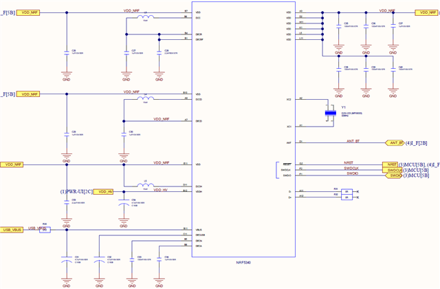
Power supply design

  • The power circuit is based on the nRF5340 DK reference design

  • The device is intended to run in High Voltage mode with a 5 V main input

  • No significant deviation from the DK power topology is intended

Is there a recommended way to verify whether the nRF5340 cores are running correctly without relying on a UART console?
For example:

  • Registers that can be safely read over JTAG

  • Power / clock / reset status indicators

  • Other hardware-visible signals that confirm core execution

thank yon.

Parents
  • Default VDD output is 1.8V, which some 3.3V J-Links don't like much - and it also not enough to light LEDs (unless they have red color).

    We have also seen this behaviour when the LF clock was not properly configured, and I don't see LFXO in your schematic. Sample code from a DK requires LFXO to be present. No idea if you also needed changes for your HFXO..?

    You can try running blinky and measure the voltage on the LED pin with a multi meter. May still need changes in the dts overlay for oscillators.

  • Thank you for the reply. I would like to add some clarifications, test results, and also ask specifically about the GPIO voltage level.

    • LFXO is present on the board
      I did not upload the LFXO schematic previously, but the board does include an LFXO.
      It is connected as shown in the attached schematic image, following the same configuration as the nRF5340 DK.

    • Firmware download via J-Link works correctly
      The firmware is successfully programmed using J-Link.
      The flashing process completes normally without any errors.

    • VDD output confirmed at 3.3 V
      I programmed the UICR with the following command:

                               nrfjprog --family nrf53 --memwr 0x00FF8010 --val 5

                After this, I measured the VDD rail and confirmed that 3.3 V is present on VDD.

    • Application core does not appear to be running
      I ran a simple LED blinky application on the application core. However:

      • The LED remains off

      • No GPIO toggling is observed

      • This suggests that the application core is not executing, even though power and flashing appear correct

  • Hi,

    Thanks for the clarification. Since you’ve set VDD to 3.3 V and flashing works, the power rail itself looks OK. The next step is to confirm whether the application core is actually leaving reset and executing. Could you please:

    These checks will tell us whether the core is being held in reset or is in a position to run your application

    Best Regards,
    Syed Maysum

Reply Children
No Data
Related