nrf54l15 combine with nrf21540

HI

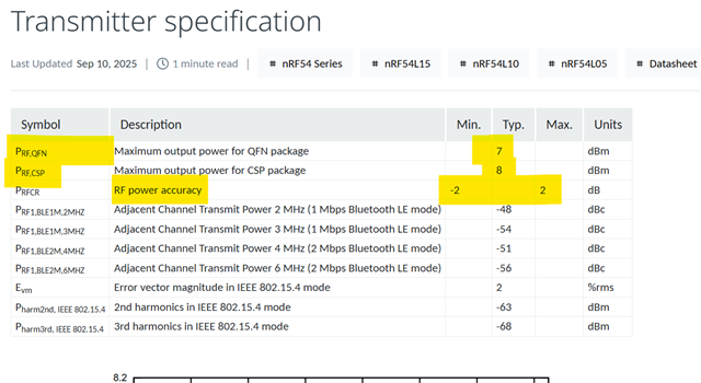
I am using the DTM example routine of NCS 3.2.1 and am currently testing the combination of nRF54L15 DK and nRF21540 EK. After flashing the original example routine to the nRF54L15 (with the nRF21540 not connected yet), I set the TP (Transmit Power) to 0 dBm via the DTM 3.1.0 application, and the spectrum analyzer detected an output power of approximately 0 dBm from the nRF54L15. However, after I added the nRF21540 configuration in the overlay file, the output power dropped to approximately -10 dBm(with the nRF21540 not connected yet),. Could this be caused by an incorrect configuration somewhere?

/ {
    chosen {
        ncs,dtm-uart = &uart20;
    };
    nrf_radio_fem: nrf21540_fem{
          compatible="nordic,nrf21540-fem";
          tx-en-gpios=<&gpio1 9 GPIO_ACTIVE_HIGH>;
          rx-en-gpios=<&gpio1 11 GPIO_ACTIVE_HIGH>;
          mode-gpios=<&gpio1 12 GPIO_ACTIVE_HIGH>;
          ant-sel-gpios=<&gpio1 10 GPIO_ACTIVE_HIGH>;
          pdn-gpios=<&gpio1 8 GPIO_ACTIVE_HIGH>;
          supply-voltage-mv=<3000>;
          trx-hold-time-us = <10>;
          pdn-settle-time-us = <17>;
          rx-en-settle-time-us = <10>;
          tx-en-settle-time-us = <10>;
    };
};
&radio {
    status = "okay";
    /* This is a number of antennas that are available on antenna matrix
     * designed by Nordic. For more information see README.rst.
     */
    dfe-antenna-num = <12>;
    /* This is a setting that enables antenna 12 (in antenna matrix designed
     * by Nordic) for PDU. For more information see README.rst.
     */
    dfe-pdu-antenna = <0x0>;

    /* These are GPIO pin numbers that are provided to
     * Radio peripheral. The pins will be acquired by Radio to
     * drive antenna switching.
     * Pin numbers are selected to drive switches on antenna matrix
     * desinged by Nordic. For more information see README.rst.
     */
    dfegpio0-gpios = <&gpio0 4 0>;
    dfegpio1-gpios = <&gpio0 5 0>;
    dfegpio2-gpios = <&gpio0 6 0>;
    dfegpio3-gpios = <&gpio0 7 0>;

    fem=<&nrf_radio_fem>;
};
CONFIG_MPSL=y
CONFIG_MPSL_FEM=y
CONFIG_MPSL_FEM_NRF21540_GPIO=y
CONFIG_MPSL_FEM_NRF21540_TX_GAIN_DB=20
CONFIG_MPSL_FEM_NRF21540_RX_GAIN_DB=13
CONFIG_MPSL_FEM_NRF21540_RUNTIME_PA_GAIN_CONTROL=y
Thanks!
Parents
  • Hi,

    Regarding your questions:

    1. Yes, when FEM is enabled, if the gain of FEM is 10 dB, and you select 10 dBm on DTM , then the output of nRF54L15 would be around 0 dBm. For the other question regarding nRF54L15 max output power, please check the datasheet, max output power is 8 dBm for CSP package and 7 dBm for QFN.


    2. For GPIO‑mode nRF21540, mode-gpios is an optional device tree property that lets MPSL control the MODE pin automatically when runtime gain control is enabled.

    If runtime gain control is disabled, the PA gain is constant and equal to CONFIG_MPSL_FEM_NRF21540_TX_GAIN_DB, and MODE can be at fixed state.

    If you see the MODE pin always high and not changing even if CONFIG_MPSL_FEM_NRF21540_RUNTIME_PA_GAIN_CONTROL is enabled, then it means the requested antenna powers never require switching between POUTA and POUTB, so the driver keeps MODE in one state.

    3. Regarding how these settings interact with each other: 

    Application / controller requests a TX power at the antenna and if FEM is enabled, MPSL FEM driver chooses which PA gain to use (POUTA or POUTB) based on the requested power and the configured gains, and then sets the SoC TX power so that SoC TX + FEM gain reaches to the requested antenna power. 
    Please note that the MODE pin is driven automatically by MPSL (for GPIO implementation) when runtime gain control is enabled and mode-gpios is present. 
    Also "CONFIG_MPSL_FEM_NRF21540_RX_GAIN_DB=13" is the gain for receiver side at FEM, it has nothing to do with TX gain and transmission power, it is for receiver side. 

  • I see it mentioned in the documentation that corresponding calibrations will be added to the power model when using SPI. Is this not applicable to standalone GPIO control?

  • Hi,
    Can you share the documentation link to the mentioned statement? 

Reply Children
No Data
Related