Hello Nordic Forums.
I have been struggling for the past couple of days to try to get the SPI working. I never thought that something this easy could have become such a nightmare.
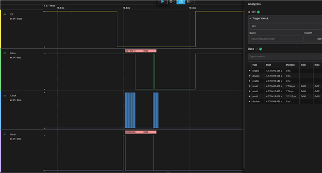
I tried compiling and running sample test from Lesson 5 of the Intermediate course (SPI). The problem with the sample is that I always get back 0xFF when I read back from the registry.
I have a bmp390 and I'd be very happy to read back a nice 0x60 value from chip id (registry 0x00), but so far all I was able to read is 0xFF, as you can see from the trace below.
This video shows something very similar to the sample files
https://www.youtube.com/watch?v=zStXcr2Fi44
I tried to write the same code and still get 0xFF. I tried to send a read 0x80 after the registry but nothing worked.
During this painful investigation, I found that for some reasons i am not even able to control some pins (ie pin 9) on the dk.
From the board configuration:
spi1_default: spi1_default {
 group1 {
     psels = <NRF_PSEL(SPIM_SCK, 0, 31)>,
             <NRF_PSEL(SPIM_MOSI, 0, 30)>,
             <NRF_PSEL(SPIM_MISO, 0, 29)>;
 };
};
While my overlay files is:
&gpio0 {
status = "okay";
};
&gpiote0 {
status = "okay";
};
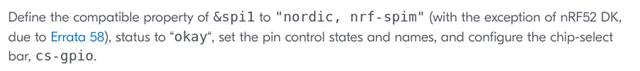
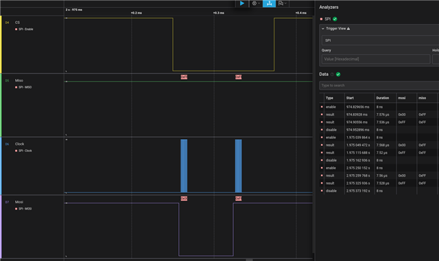
&spi1 {
compatible = "nordic,nrf-spi";
status = "okay";
};
/ {
cs_one_pin: cs-one-pin {
compatible = "nordic,gpio-pins";
gpios = <&gpio0 11 GPIO_ACTIVE_LOW>;
status = "okay";
};
};
Here is my main.c file
#include <stdio.h>
#include <zephyr/kernel.h>
#include <zephyr/drivers/gpio.h>
#include <zephyr/drivers/spi.h>
#include <zephyr/device.h>
#include <zephyr/devicetree.h>

#define SLEEP_TIME_MS 1000
#define LED0_NODE DT_ALIAS(led0)
#define SPI1_NODE DT_NODELABEL(spi1)

static const struct device *spi1_dev = DEVICE_DT_GET(SPI1_NODE);
static const struct gpio_dt_spec led = GPIO_DT_SPEC_GET(LED0_NODE, gpios);
static const struct gpio_dt_spec cs = GPIO_DT_SPEC_GET_OR(DT_NODELABEL(cs_one_pin), gpios, {0});

static struct spi_config spi_cfg = {
 .frequency = 1000000U,
 .operation = SPI_WORD_SET(8),
 .slave = 0
};

static void readRegister(uint8_t reg, uint8_t values[], uint8_t size)
{
 int err;
 uint8_t tx_buffer[1];
 tx_buffer[0] = reg;

 struct spi_buf tx_spi_bufs[] = {
    {.buf = tx_buffer, .len = sizeof(tx_buffer)}
 };

 struct spi_buf_set spi_tx_buf_set = {
 .buffers = tx_spi_bufs,
 .count = 1
 };

 struct spi_buf rx_spi_bufs[] = {
    {.buf = values, .len = size}
 };

 struct spi_buf_set spi_rx_buf_set = {
 .buffers = rx_spi_bufs,
 .count = 1
 };

 gpio_pin_set_dt(&cs, 1U);

 do {
    err = spi_write(spi1_dev, &spi_cfg, &spi_tx_buf_set);
    if(err < 0)
    {
     break;
    }
     err = spi_read(spi1_dev, &spi_cfg, &spi_rx_buf_set);
    }
    while(false);
    gpio_pin_set_dt(&cs, 0U);
  }

static void readChipID(void) {
 uint8_t rx_buf_chipid[1];
 readRegister(0x00, rx_buf_chipid, 1);
}

int main(void)
{
 int ret;
 bool led_state = true;
 if (!gpio_is_ready_dt(&led)) {
    return 0;
 }
 if(!device_is_ready(spi1_dev)) {
    return 0;
 }
 ret = gpio_pin_configure_dt(&led, GPIO_OUTPUT_ACTIVE);
 if (ret < 0) {
    return 0;
 }
 ret = gpio_pin_configure_dt(&cs, GPIO_OUTPUT);
 if (ret < 0) {
    return 0;
 }
 while (1) {
    ret = gpio_pin_toggle_dt(&led);
    if (ret < 0) {
        return 0;
    }
    readChipID();
    printf("LED state: %s\n", led_state ? "ON" : "OFF");
    k_msleep(SLEEP_TIME_MS);
 }
 return 0;
}
Any idea of what I am doing wrong?
I apologize for all these information, but I hope it will help others having the same issues.
Thank you