Hardware PWM doesn't operate with 100% duty cycle

Hello

I'm currently working SDK upgrade from ncs v2.6.4 to v3.2.1

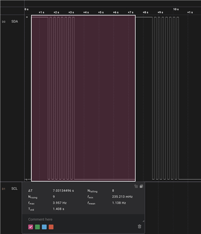
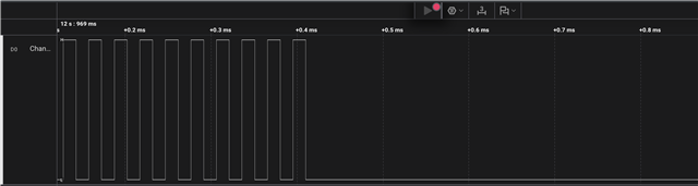
I found that, in fade in/out scenario, the PWM works well. however, if it need to turn on in 100%duty cycle, it doesn't turned on.

When I compare both driver implementation in sdk, I found a suspicious part.

Path: **zephyr/drivers/pwm/pwm_nrfx.c**

line 202:207

	} else if (pulse_cycles >= period_cycles) {
		/* Constantly active (duty 100%). */
		/* This value is always greater than or equal to COUNTERTOP. */
		compare_value = PWM_NRFX_CH_COMPARE_MASK;
		needs_pwm = IS_ENABLED(NRF_PWM_HAS_IDLEOUT) &&
			    IS_ENABLED(CONFIG_PWM_NRFX_NO_GLITCH_DUTY_100);
	} else {

Could you tell me there is similar issue or solution to solve this problem?

Best regards,
Woo-chan Kim

Parents
  • Hi,


    As per the code, if you check further down in the same function that you copied code from, it will disable the pwm module, and use nrf_gpio to set it to a high or low level, based on if you input 100% or 0 % duty cycle.

    Here is a quick test, based on zephyr/samples/basic/blink_pwm:

    /*
     * Copyright (c) 2016 Intel Corporation
     * Copyright (c) 2020 Nordic Semiconductor ASA
     *
     * SPDX-License-Identifier: Apache-2.0
     */
    
    /**
     * @file Sample app to demonstrate PWM.
     */
    
    #include <zephyr/kernel.h>
    #include <zephyr/sys/printk.h>
    #include <zephyr/device.h>
    #include <zephyr/drivers/pwm.h>
    
    static const struct pwm_dt_spec pwm_led0 = PWM_DT_SPEC_GET(DT_ALIAS(pwm_led0));
    
    #define MIN_PERIOD PWM_SEC(1U) / 128U
    #define MAX_PERIOD PWM_SEC(1U)
    
    int main(void)
    {
    	uint32_t max_period;
    	uint32_t period;
    	uint8_t dir = 0U;
    	int ret;
    
    	printk("PWM-based blinky\n");
    
    	if (!pwm_is_ready_dt(&pwm_led0)) {
    		printk("Error: PWM device %s is not ready\n",
    		       pwm_led0.dev->name);
    		return 0;
    	}
    
    	/*
    	 * In case the default MAX_PERIOD value cannot be set for
    	 * some PWM hardware, decrease its value until it can.
    	 *
    	 * Keep its value at least MIN_PERIOD * 4 to make sure
    	 * the sample changes frequency at least once.
    	 */
    	printk("Calibrating for channel %d...\n", pwm_led0.channel);
    	max_period = MAX_PERIOD;
    	while (pwm_set_dt(&pwm_led0, max_period, max_period / 2U)) {
    		max_period /= 2U;
    		if (max_period < (4U * MIN_PERIOD)) {
    			printk("Error: PWM device "
    			       "does not support a period at least %lu\n",
    			       4U * MIN_PERIOD);
    			return 0;
    		}
    	}
    
    	printk("Done calibrating; maximum/minimum periods %u/%lu nsec\n",
    	       max_period, MIN_PERIOD);
    
    	period = max_period;
    	while (1) {
    		/* Set 100% for 1 sec */
    		ret = pwm_set_dt(&pwm_led0, period, period);
    		if (ret) {
    			printk("ret: %d\n", ret);
    		}
    		k_sleep(K_SECONDS(1U));
    		/* 50 % for 2 sec */
    		ret = pwm_set_dt(&pwm_led0, period, period / 2U);
    		if (ret) {
    			printk("ret: %d\n", ret);
    		}
    		k_sleep(K_SECONDS(2U));
    		/* 0 % for 4 sec */
    		ret = pwm_set_dt(&pwm_led0, period, 0);
    		if (ret) {
    			printk("ret: %d\n", ret);
    		}
    		k_sleep(K_SECONDS(4U));
    	}
    	return 0;
    }
    

    Which behaves like this: 


    Kind regards,

    Håkon

  • Thanks for your reply.

    When I fixed using the `sw_pwm` periperal that you recommend by refer the sample,

    it makes error like this.

    /opt/nordic/ncs/v3.2.1/zephyr/drivers/pwm/pwm_nrf_sw.c:420:9: error: invalid operands to binary & (have 'nrfx_gpiote_t *' and 'nrfx_gpiote_t')
      420 |         &GPIOTE_NRFX_INST_BY_NODE(NRF_DT_GPIOTE_NODE_BY_IDX(_node_id, _prop, _idx))
          |         ^
    /Users/woochankim/Project/Firmware-Sense1-Guardian/build_development/Firmware-Sense1-Guardian/zephyr/include/generated/zephyr/devicetree_generated.h:8654:9: note: in expansion of macro 'GPIOTE_AND_COMMA'
     8654 |         fn(DT_N_S_sw_pwm, channel_gpios, 1) \
          |         ^~
    /opt/nordic/ncs/v3.2.1/zephyr/include/zephyr/devicetree.h:5499:33: note: in expansion of macro 'DT_N_S_sw_pwm_P_channel_gpios_FOREACH_PROP_ELEM'
     5499 | #define DT_CAT4(a1, a2, a3, a4) a1 ## a2 ## a3 ## a4
          |                                 ^~
    /opt/nordic/ncs/v3.2.1/zephyr/include/zephyr/devicetree.h:5271:9: note: in expansion of macro 'DT_FOREACH_PROP_ELEM'
     5271 |         DT_FOREACH_PROP_ELEM(DT_DRV_INST(inst), prop, fn)
          |         ^~~~~~~~~~~~~~~~~~~~
    /opt/nordic/ncs/v3.2.1/zephyr/drivers/pwm/pwm_nrf_sw.c:425:17: note: in expansion of macro 'DT_INST_FOREACH_PROP_ELEM'
      425 |                 DT_INST_FOREACH_PROP_ELEM(0, channel_gpios, GPIOTE_AND_COMMA)
          |                 ^~~~~~~~~~~~~~~~~~~~~~~~~
    ninja: build stopped: subcommand failed.

    I need to control 3 channel pwm to implement full color led.

    this is the overlay that i used to.

    &pwm0 {
        status = "disabled";
    };
    
    &sw_pwm {
        status = "okay";
        channel-gpios = <&gpio1 4 PWM_POLARITY_INVERTED>,
                        <&gpio1 5 PWM_POLARITY_INVERTED>,
                        <&gpio1 6 PWM_POLARITY_INVERTED>;
    };
    
    pwmleds {
        compatible = "pwm-leds";
        pwm_green: pwm_led_0 {
            pwms = <&sw_pwm 0 PWM_MSEC(20) PWM_POLARITY_INVERTED>;
        };
        pwm_blue: pwm_led_1 {
            pwms = <&sw_pwm 1 PWM_MSEC(20) PWM_POLARITY_INVERTED>;
        };
        pwm_red: pwm_led_2 {
            pwms = <&sw_pwm 2 PWM_MSEC(20) PWM_POLARITY_INVERTED>;
        };
    };

    could you help me to solve this problem.

    If you can, please tell me why I need to use the `sw_pwm`?

    Because, In previous SDK version, the pwm works well.

Reply
  • Thanks for your reply.

    When I fixed using the `sw_pwm` periperal that you recommend by refer the sample,

    it makes error like this.

    /opt/nordic/ncs/v3.2.1/zephyr/drivers/pwm/pwm_nrf_sw.c:420:9: error: invalid operands to binary & (have 'nrfx_gpiote_t *' and 'nrfx_gpiote_t')
      420 |         &GPIOTE_NRFX_INST_BY_NODE(NRF_DT_GPIOTE_NODE_BY_IDX(_node_id, _prop, _idx))
          |         ^
    /Users/woochankim/Project/Firmware-Sense1-Guardian/build_development/Firmware-Sense1-Guardian/zephyr/include/generated/zephyr/devicetree_generated.h:8654:9: note: in expansion of macro 'GPIOTE_AND_COMMA'
     8654 |         fn(DT_N_S_sw_pwm, channel_gpios, 1) \
          |         ^~
    /opt/nordic/ncs/v3.2.1/zephyr/include/zephyr/devicetree.h:5499:33: note: in expansion of macro 'DT_N_S_sw_pwm_P_channel_gpios_FOREACH_PROP_ELEM'
     5499 | #define DT_CAT4(a1, a2, a3, a4) a1 ## a2 ## a3 ## a4
          |                                 ^~
    /opt/nordic/ncs/v3.2.1/zephyr/include/zephyr/devicetree.h:5271:9: note: in expansion of macro 'DT_FOREACH_PROP_ELEM'
     5271 |         DT_FOREACH_PROP_ELEM(DT_DRV_INST(inst), prop, fn)
          |         ^~~~~~~~~~~~~~~~~~~~
    /opt/nordic/ncs/v3.2.1/zephyr/drivers/pwm/pwm_nrf_sw.c:425:17: note: in expansion of macro 'DT_INST_FOREACH_PROP_ELEM'
      425 |                 DT_INST_FOREACH_PROP_ELEM(0, channel_gpios, GPIOTE_AND_COMMA)
          |                 ^~~~~~~~~~~~~~~~~~~~~~~~~
    ninja: build stopped: subcommand failed.

    I need to control 3 channel pwm to implement full color led.

    this is the overlay that i used to.

    &pwm0 {
        status = "disabled";
    };
    
    &sw_pwm {
        status = "okay";
        channel-gpios = <&gpio1 4 PWM_POLARITY_INVERTED>,
                        <&gpio1 5 PWM_POLARITY_INVERTED>,
                        <&gpio1 6 PWM_POLARITY_INVERTED>;
    };
    
    pwmleds {
        compatible = "pwm-leds";
        pwm_green: pwm_led_0 {
            pwms = <&sw_pwm 0 PWM_MSEC(20) PWM_POLARITY_INVERTED>;
        };
        pwm_blue: pwm_led_1 {
            pwms = <&sw_pwm 1 PWM_MSEC(20) PWM_POLARITY_INVERTED>;
        };
        pwm_red: pwm_led_2 {
            pwms = <&sw_pwm 2 PWM_MSEC(20) PWM_POLARITY_INVERTED>;
        };
    };

    could you help me to solve this problem.

    If you can, please tell me why I need to use the `sw_pwm`?

    Because, In previous SDK version, the pwm works well.

Children
  • Hi,


    Sorry, forgot to mention that you should rename/delete that file for the purpose of this testing.

    Woo-chan Kim said:

    When I fixed using the `sw_pwm` periperal that you recommend by refer the sample,

    blinky_pwm defines that specifically for the nrf5340dk_nrf5340_cpuapp.overlay board. You can safely use "normal" pwm with it, by deleting that file.

    Check this by searching for "CONFIG_PWM_NRFX" in build/blinky_pwm/zephyr/.config file, and if this is set to 'y'; then "NRF_PWM" hardware peripheral is used.


    Woo-chan Kim said:

    I need to control 3 channel pwm to implement full color led.

    sw_pwm is made specifically for 1 channel. Having several will cause issues, as explained here:

     RE: How to use two sw_pwm instances with nrf5340 with Zephyr? 


    Kind regards,

    Håkon

  • Hi Hakon,

    I'm having a similar issue on an nRF54LM20 although the issue seems more driver related than hardware related. It seems to be an interaction with CONFIG_PM_DEVICE_RUNTIME. When enabled, as soon as the pwm api call is finished, the pm subsystem puts the pinctrl node to sleep. This only seems to happen when i set the duty cycle to 100% and it happens whether or not  zephyr,pm-device-runtime-auto is on the pwm node.

    node:

    &pwm20 {
        status = "okay";
        pinctrl-0 = <&pwm20_default>;
        pinctrl-1 = <&pwm20_sleep>;
        pinctrl-names = "default", "sleep";
    };
    
        pwm20_default: pwm20_default {
            group1 {
                psels = <NRF_PSEL(PWM_OUT0, 1, 17)>,
                    <NRF_PSEL(PWM_OUT1, 1, 18)>;
                nordic,invert;
            };
        };
    
        pwm20_sleep: pwm20_sleep {
            group1 {
                psels = <NRF_PSEL(PWM_OUT0, 1, 17)>,
                    <NRF_PSEL(PWM_OUT1, 1, 18)>;
                low-power-enable;
            };
        };

    console:

    uart:~$ pwm usec pwm@d2000 0 30 15 # duty to 50%
    uart:~$ pwm usec pwm@d2000 0 30 30 # duty to 100%

    logic analyzer:

  • Hi,


    I am not sure I fully understand the scenario. Your picture shows that the pin goes low after you set it to 100% DC, which is expected per your device tree settings. Trace output shows 50%, then 100%.

    The pin has the "nordic,invert", which will set the active state low:

    https://github.com/nrfconnect/sdk-zephyr/blob/main/dts/bindings/pinctrl/nordic%2Cnrf-pinctrl.yaml#L118-L122


    Could you please create a dedicated ticket for the matter? Please feel free to share more details, especially if this is related to PM_DEVICE_RUNTIME.


    Kind regards,

    Håkon

  • My understanding was that nordic,invert is used on all ncs pwm pinctrl samples because the peripheral is active low by default. nordic,invert makes these pins active high which is more intuitive. If I do `pwm usec pwm@d2000 0 30 0 # duty to 0%` then the pin still goes low. When PM_DEVICE_RUNTIME is disabled and i set the duty cycle to 100 the pin goes high as expected.

    I can create a seperate ticket with more details.

Related