Minimizing quiescent current on nRF54L15 and nRF7002 design with shared antenna

Good day,

We are developing a board with a nRF54L15 + nRF7002 for BLE and WiFi connectivity.

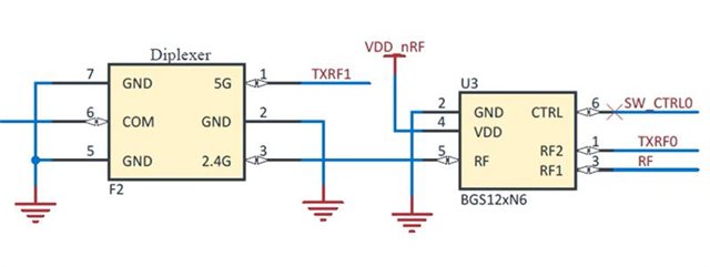
The Nordic nRF54L15 + nRF7002 reference design has been a good starting point. It demonstrates the use of a single antenna for WiFi and BLE, using a BGS12SN6 RF switch to connect either RF input to the antenna.

The downside of the RF switch is that it introduces a quiescent current of 63 uA (typ, datasheet) at all times when powered on. The reference design connects the RF switch directly to the main power supply.

What is the recommended approach to reduce power consumption of the RF switch when not in use? Can VDD be controlled by the MPSL CX/FEM API and are there any examples for this?

Note: This ticket looks related:  Quiescent current - Thingy:91X vs. Thingy:91 with BLE enabled , however the conclusion is that:

This switch is used to select whether the 2.4 GHz antenna is used for Wi-Fi or BLE. When BLE is enabled in the connectivity bridge, the switch is continuously powered, since the time to turn on the load switch U5, which in turn powers the RF switch, is too long (hundreds of µs) to toggle it dynamically using the BLE stack.

This would appear to contradict the datasheet for the BGS12WN6 - The typ. power up setting time is 5.8 us, well below the 40 us TX_RAMP_UP_TIME described as the maximum allowable for dynamic control of RF FEM: https://docs.nordicsemi.com/bundle/ncs-2.6.4/page/nrf/device_guides/working_with_fem.html

Looking forward to your feedback.

Dom

Parents
  • Hello,

    This switch is used to select whether the 2.4 GHz antenna is used for Wi-Fi or BLE. When BLE is enabled in the connectivity bridge, the switch is continuously powered, since the time to turn on the load switch U5, which in turn powers the RF switch, is too long (hundreds of µs) to toggle it dynamically using the BLE stack.

    This would appear to contradict the datasheet for the BGS12WN6 - The typ. power up setting time is 5.8 us, well below the 40 us TX_RAMP_UP_TIME described as the maximum allowable for dynamic control of RF FEM: https://docs.nordicsemi.com/bundle/ncs-2.6.4/page/nrf/device_guides/working_with_fem.html

    I think you are missing the reference to load switch U5, which has a turn-on time of several hundreds of us.

    What is the recommended approach to reduce power consumption of the RF switch when not in use? Can VDD be controlled by the MPSL CX/FEM API and are there any examples for this?

    Unfortunately I can't find any direct way of knowing if radio X/Y do RX/TX at any given time, so I don't have a good way to do what you request no. Maybe it is possible to use the coex signal from the nRF7002 in combinations with radio notification internally of the nRF54L15 to find roughly when radio will be TX/RX.

    Kenneth

  • For argument's sake let's say that a PMOS like the BSS84F is used to control VDD to the RF switch, so that the turn on time of the PMOS plus setting time of the RF switch (BGS12WN6) is roughly 7 uS.

    This delay can be accounted for on the BLE side by using the FEM API's ramp time parameter. However, I see no similar way to adjust the timing of the nRF7002's control signal before the start of TX/RX on the WiFi MCU.

    I suppose a compromise could be to control the RF switch dynamically when the WiFi MCU is off (via FEM API) and to keep it on at all times when WiFi is active. Do you spot any problems with this?

    Please let me know of other suggestions to reduce power consumption on a shared-antenna design.

    Dom

Reply
  • For argument's sake let's say that a PMOS like the BSS84F is used to control VDD to the RF switch, so that the turn on time of the PMOS plus setting time of the RF switch (BGS12WN6) is roughly 7 uS.

    This delay can be accounted for on the BLE side by using the FEM API's ramp time parameter. However, I see no similar way to adjust the timing of the nRF7002's control signal before the start of TX/RX on the WiFi MCU.

    I suppose a compromise could be to control the RF switch dynamically when the WiFi MCU is off (via FEM API) and to keep it on at all times when WiFi is active. Do you spot any problems with this?

    Please let me know of other suggestions to reduce power consumption on a shared-antenna design.

    Dom

Children
  • Hi,

    Dominic said:
    I suppose a compromise could be to control the RF switch dynamically when the WiFi MCU is off (via FEM API) and to keep it on at all times when WiFi is active. Do you spot any problems with this?

    I don't have a better suggestion at least, it's not something we have tried or looked into.

    Not directly related to your question, but please be aware we found an issue in the schematic:

    We noticed that the SW_CTRL0 net has to be pulled down. We will correct the schematics and upload soon on nRF7002 - Downloads - nordicsemi.com.

    Kenneth

  • Yes I saw this issue too. SW_CTRL0 is otherwise floating when the wifi MCU is off.

    Thanks for your help. I may follow up with Nordic internally to check if there is roadmap for a FEM API on the nRF7002.
    For now we will proceed with the dynamic control of RF switch when WiFi is off and ‘always on’ when WiFi is enabled. 

    Dom

Related