can't find board nrf52833dk_nrf5283 in bluetooth DTM sample

Hello,

I have a project in Visual studio code and Nrf connect.
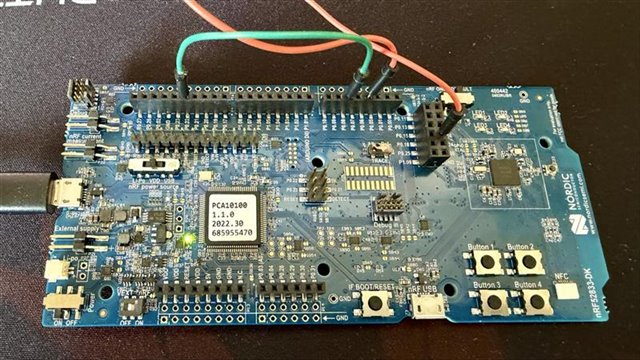
MCU is a NRF 52833.

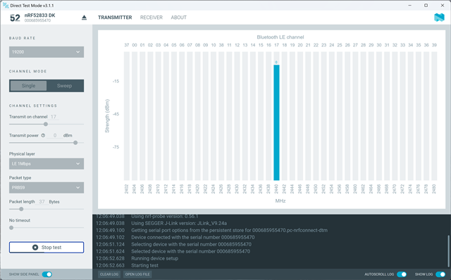
For the certicications, the lab request me the DTM mode.

I tried the use the Sample - Direct-test-mode Firmware

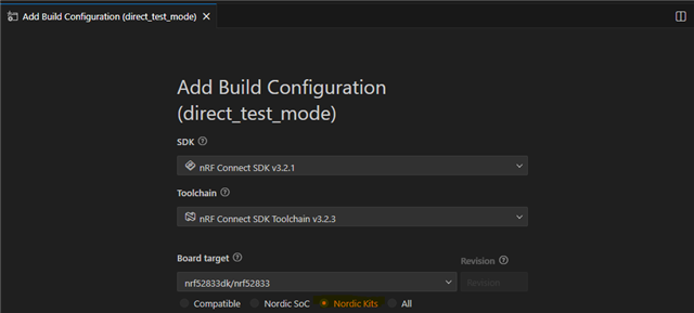
However I'm not able to find eht board "nrf52833dk_nrf5283" in the NCS folder.

I tried to install several SDKs (2.2.0 / 2.3.0 / 2.4.2 / 2.7.0 / 2.9.2 / 3.2.4 ) but none includes the 833 board. I can find and compile with the 840, but no options for the 833.

Please can sombody help me ? I need to use and compile the DTM for the 52833.

Thanks in advance

Parents
  • Hi,

    If you choose Nordic Kits you can build for nRF52833dk like this:

    But I assume you are not using direction finding, so you need to disable it by either adding to app.overlay:

    &radio {
    	/delete-property/ dfe-supported;
    };

    Or build as described here: 
    https://docs.nordicsemi.com/bundle/ncs-latest/page/nrf/samples/bluetooth/direct_test_mode/README.html#disabling_direction_finding_feature 

    Kenneth

  • hello, thanks for your reply, however, with the Nordic Kit selection, (and not the Compatible), impossible to compile the code...

    I can compile selecting the nRF52840 only...

    how to get just a simple code for DTM for the 833 ?

    Also don't you have example with the USB communication ?

    I can't understant how all people using nrf devices have to certificate them then every body have to use the DTM too... nothing is proposed for this ? I mean PC software - USB control and DTM for most nrf devices ?

    So in my case, I need to create a new board to use with the DTM as the 52833 is not available...right ?

  • Hello,

    thanks for the code, however, after many tests, I saw:

    1- All of the nordic samples codes are working on the DK

    2- All of the nordic samples codes are crashing (not initializing) on my custom PCB.

    3- Only my custom FW is working on my custom PCB.

    The HW is quite same ( 32K not mouted on both, 32M mounted on both)

    Also an important new point I saw: I tried the simple blinky code from Nordic. It only initialize a output and blink this output.

    Issue is same (working on DK but not on my PCB). BUT if I use the debug mode in nrf connect, with the segger flasher connected, I start the debug, in this case the application is working even when I disconnect the segger. 

    So starting in debug with segger is working, but MCU starting by himself is crashing.

    could it be some settings ? how to solve this issue ? 

  • Hello,

    christopheMon said:
    BUT if I use the debug mode in nrf connect, with the segger flasher connected, I start the debug, in this case the application is working even when I disconnect the segger. 

    That was useful information yes, I can now see that you don't have DCDC circuitry in your design. It will default to LDO when debugging, so please add the following to the overlay file and try again:

    &reg1 {
        regulator-initial-mode = <NRF5X_REG_MODE_LDO>;
    };

    Updated the example also:

    radio_test_ncs_v3.2.4_ldo.zip

    Kenneth

  • ohhh nice this make my PCB working with the standard Radio test sample.

    perfect ....thank you ...

    Just before closing the topic, can you tell me which command make/refer to each lines https://docs.nordicsemi.com/bundle/ncs-latest/page/nrf/samples/peripheral/radio_test/README.html#user_interface

    • Selection of TX and RX modes

    • Selection of BLE channels:

         o Lowest channel

         o Middle channel

         o Highest channel

    • Continuous transmission with duty cycle ≥ 98%

    • Transmission at maximum power

    • PRBS9 modulation

    • Standalone operation, without dependence on the mobile application

  • Hello Kennet, 

    after checking with lab, they are not accepting the radio test, they really need the DTM implemented, as the goal is to certificate wildword the device, and they en the DTM that is only used by any labs.

    I tried to compilate the DTM sample, but unfortunately, it didn't build correctly witht the nRF52833dk_nrf52833 board... can you check this ?

  •  Hello,

    After spending time on this, the Radio test is now working on my custom PCB, but as said, the lab request me the DTM instead of the radio mode.

    I compiled the DTM sample code for my custom PCB (only possible with SDK 2.9.2 and toolchain 3.2.4, others are not building!), I can flash it and comunicate with by uart.

    However, when trying to test DTM with 2 devices, one transmitting [0x80 0x00], second device receiving [0x40 0x25], after some seconde, when I stop the receiving [0xC0 0x00], it returns the code 0x80 0x00, this means receiver hasn't see any correct packets. on the transmitter, on stop, it reply the good number of sent packets.

    The interesting point is :the transmitter reply the number of sent packet only when the receiver in in receive mode, otherwise it reply also 0x80 0x00.

    Why ? normally the receiver must reply the same number of sent packets ??

    What doese it means ? any FW issues ? 

Reply
  •  Hello,

    After spending time on this, the Radio test is now working on my custom PCB, but as said, the lab request me the DTM instead of the radio mode.

    I compiled the DTM sample code for my custom PCB (only possible with SDK 2.9.2 and toolchain 3.2.4, others are not building!), I can flash it and comunicate with by uart.

    However, when trying to test DTM with 2 devices, one transmitting [0x80 0x00], second device receiving [0x40 0x25], after some seconde, when I stop the receiving [0xC0 0x00], it returns the code 0x80 0x00, this means receiver hasn't see any correct packets. on the transmitter, on stop, it reply the good number of sent packets.

    The interesting point is :the transmitter reply the number of sent packet only when the receiver in in receive mode, otherwise it reply also 0x80 0x00.

    Why ? normally the receiver must reply the same number of sent packets ??

    What doese it means ? any FW issues ? 

Children
Related