
This is my first time designing rf curcuit.
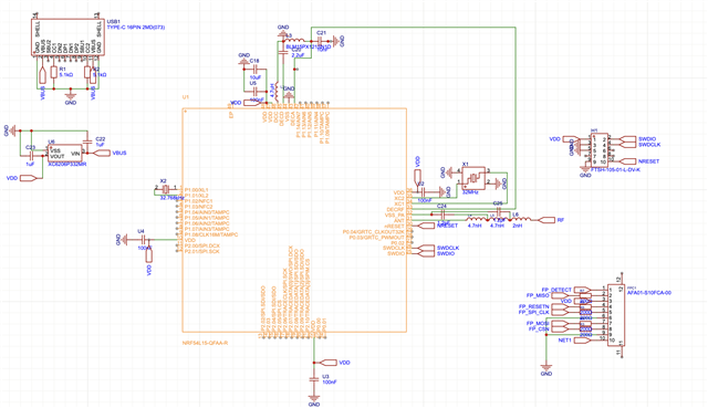
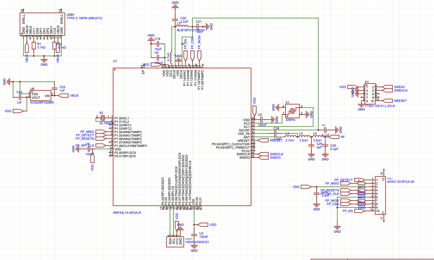
I refered to reference curcuit on datasheet
This is my first time designing rf curcuit.
I refered to reference curcuit on datasheet

Hi,
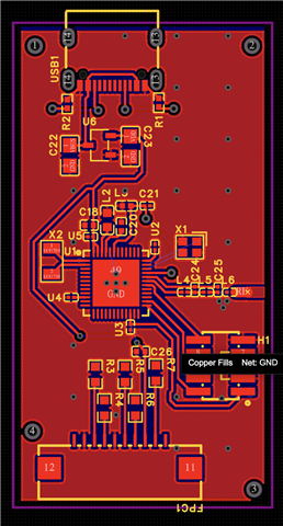
Looks like there are still a few connections missing on the layout side like the 32MHz crystal. Its best to copy the reference design if possible, then it will just work, and you seem to have the space for it.
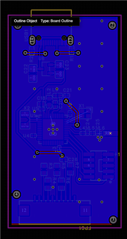
For the nRF54L series you need 4 layers and make sure the first innner layer is no more then 100um from the top.
Its a good start but a few things are missing, like you do not actually have a antenna, so that needs to be added if you want to have any rage, maybe you would get 1 cm range with the current setup.
Here are some links that I think are good that you can go through and once you have done that you can update here with the changes and I will go over everything to make sure it is ok.
PCB Antenna - How To Design, Measure And Tune
https://devzone.nordicsemi.com/guides/hardware-design-test-and-measuring/b/nrf5x/posts/general-pcb-design-guidelines-for-nrf53-series
This is not up to date for the 54 series specifically but it covers all the basics.
Here is some info:
Antenna info:
the reference design can be found under the product page on our website.
General design guidelines for the nRF51 series can be found on DevZone.
An alternative is to look at the 52 series, where the radio needs fewer external components, to make it more suitable for a smaller design.
General design guidelines for the nRF52 series
nRF52 dongle
Antenna choice is complex and depends on many factors including technical and commercial considerations. But here are some info:
Monopole, printed PCB antenna: This is easy to make and easy to tune, you also only need one impedance matching component, so it’s cost effective. Here the spacing is the issues, you need to make it about 23 mm long needs a minimum of 5 mm clearance to the ground plane. High bandwidth, making it fairly resistant to detuning. Link to our whitepaper: https://infocenter.nordicsemi.com/pdf/nwp_008.pdf?cp=12_18
Meander antenna, printed PCB antenna, ex. our dongle antenna design: Requires a smaller area than the monopole antenna, but usually requires a pi-network for tuning in addition to length. Lower bandwidth than a quarter wave monopole antenna. Here is a link to our nRF52840 Dongle design files as an example of this: https://www.nordicsemi.com/Software-and-Tools/Development-Kits/nRF52840-Dongle/Download#infotabs
Chip antenna: Higher BOM, but the antenna is small. The downside is that it usually has less gain. It requires a matching network, based on the vendors recommendations. It has a lower bandwidth than a quarter wave monopole antenna so it can be sensitive to detuning.
Considering your target of a very small form factor a chip Antenna makes sense but reducing antenna size most often results in reduced performance. Some of the parameters that suffer are:
Reduced efficiency (or gain)
Shorter range
Smaller bandwidth
Distorted radiation pattern
More critical tuning
Increased sensitivity to component and PCB spread
Increased sensitivity to external factors (“body” effect, ground plane etc.)
It is often better not to reduce antenna size too much, if you can avoid it.
As a rule we do not usually recommend specific chip antennas. The selection will depend very much on the end application design, the antenna vendors can assist on choosing the right antenna for a specific design, for example Johanson has a useful tool that helps with this selection: https://www.johansontechnology.com/chip-antenna-selection
Hi,
Looks like there are still a few connections missing on the layout side like the 32MHz crystal. Its best to copy the reference design if possible, then it will just work, and you seem to have the space for it.
For the nRF54L series you need 4 layers and make sure the first innner layer is no more then 100um from the top.
Its a good start but a few things are missing, like you do not actually have a antenna, so that needs to be added if you want to have any rage, maybe you would get 1 cm range with the current setup.
Here are some links that I think are good that you can go through and once you have done that you can update here with the changes and I will go over everything to make sure it is ok.
PCB Antenna - How To Design, Measure And Tune
https://devzone.nordicsemi.com/guides/hardware-design-test-and-measuring/b/nrf5x/posts/general-pcb-design-guidelines-for-nrf53-series
This is not up to date for the 54 series specifically but it covers all the basics.
Here is some info:
Antenna info:
the reference design can be found under the product page on our website.
General design guidelines for the nRF51 series can be found on DevZone.
An alternative is to look at the 52 series, where the radio needs fewer external components, to make it more suitable for a smaller design.
General design guidelines for the nRF52 series
nRF52 dongle
Antenna choice is complex and depends on many factors including technical and commercial considerations. But here are some info:
Monopole, printed PCB antenna: This is easy to make and easy to tune, you also only need one impedance matching component, so it’s cost effective. Here the spacing is the issues, you need to make it about 23 mm long needs a minimum of 5 mm clearance to the ground plane. High bandwidth, making it fairly resistant to detuning. Link to our whitepaper: https://infocenter.nordicsemi.com/pdf/nwp_008.pdf?cp=12_18
Meander antenna, printed PCB antenna, ex. our dongle antenna design: Requires a smaller area than the monopole antenna, but usually requires a pi-network for tuning in addition to length. Lower bandwidth than a quarter wave monopole antenna. Here is a link to our nRF52840 Dongle design files as an example of this: https://www.nordicsemi.com/Software-and-Tools/Development-Kits/nRF52840-Dongle/Download#infotabs
Chip antenna: Higher BOM, but the antenna is small. The downside is that it usually has less gain. It requires a matching network, based on the vendors recommendations. It has a lower bandwidth than a quarter wave monopole antenna so it can be sensitive to detuning.
Considering your target of a very small form factor a chip Antenna makes sense but reducing antenna size most often results in reduced performance. Some of the parameters that suffer are:
Reduced efficiency (or gain)
Shorter range
Smaller bandwidth
Distorted radiation pattern
More critical tuning
Increased sensitivity to component and PCB spread
Increased sensitivity to external factors (“body” effect, ground plane etc.)
It is often better not to reduce antenna size too much, if you can avoid it.
As a rule we do not usually recommend specific chip antennas. The selection will depend very much on the end application design, the antenna vendors can assist on choosing the right antenna for a specific design, for example Johanson has a useful tool that helps with this selection: https://www.johansontechnology.com/chip-antenna-selection

BOM_Board1_PCB1_2026-03-30.xlsx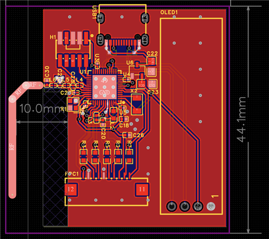
Thank you for helping me!
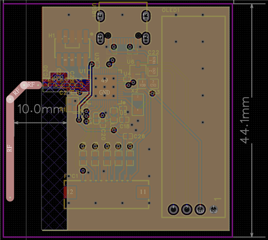
RF line is 25mm long and has 1.5mm Width with spacing 10mm from gnd plane!
is it good??
Hi,
This is looks a lot better, but a few pointers still:
Yeonjun Lee said:RF line is 25mm long and has 1.5mm Width with spacing 10mm from gnd plane!
The implementation of the antenna here looks ok, its always possible to add some extra length to the antenna and cut the length down for tuning of the antenna for a better match.
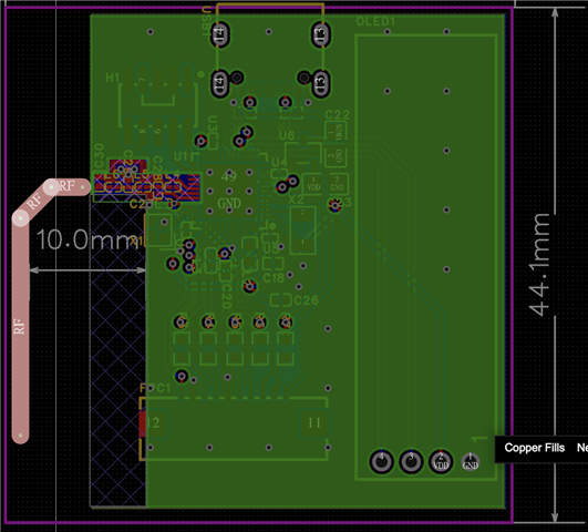
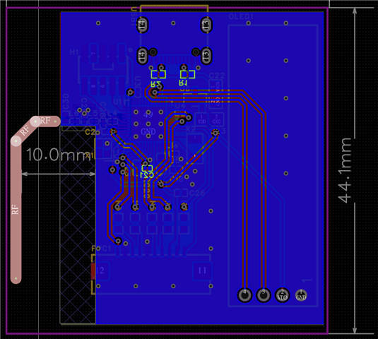
I would add more via connections all over the PCB to tie the different GND layers together.
See: https://www.altium.com/documentation/altium-designer/pcb/via-stitching-via-shielding#via_style as an example on how to implement via stitching and fencing.
For the transmission line here I would like to see a full co-planar wave guide, so ground on both sides, so marked in green here on the other side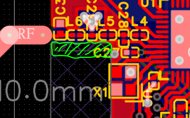
I still think there is room to copy the ref design layout exactly, this will make things easier and the likelihood of unwanted performance loss or issues. 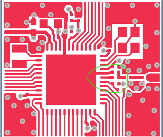
Having the radio matching component close to the nRF54L15 should be prioritized.
Regards,
Jonathan