i have a trivially simple "bare-metal" (register-level) test case in which i setup GRTC as follows:
MODE.SYSCOUNTEREN = 1
TASKS.START = 1
TIMEOUT = 2
i also have the LFXTAL configured as my LFCLK....
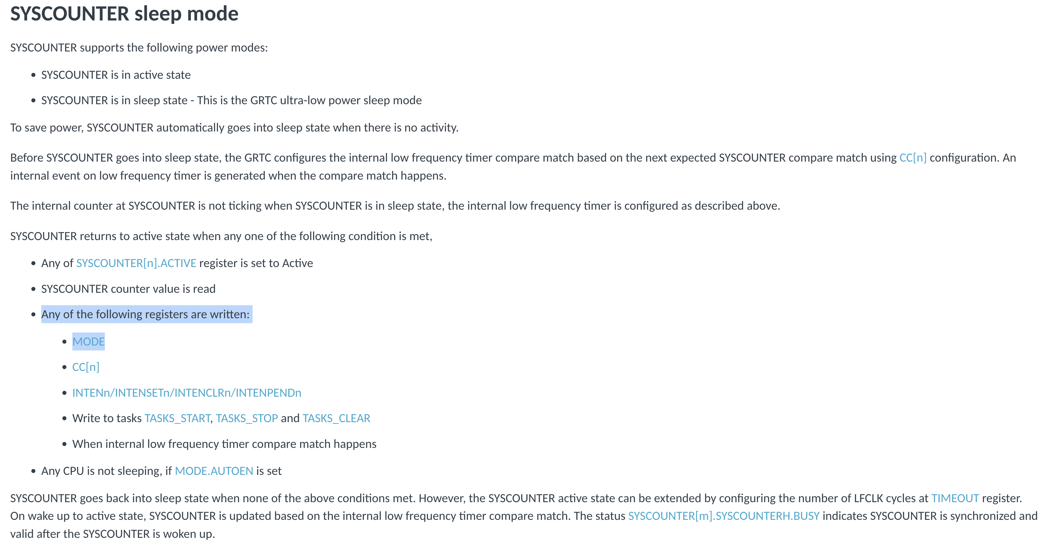
after this, i go into an *indefinite* sleep.... no GRTC wakeups have been scheduled....
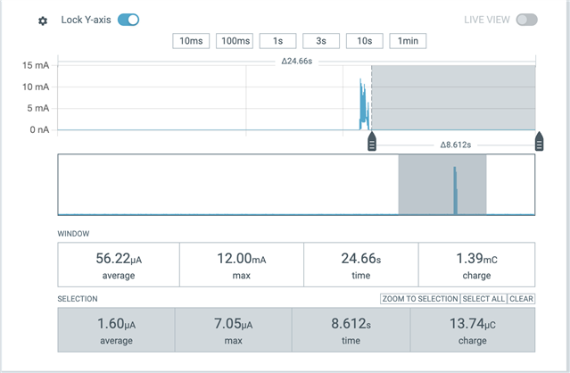
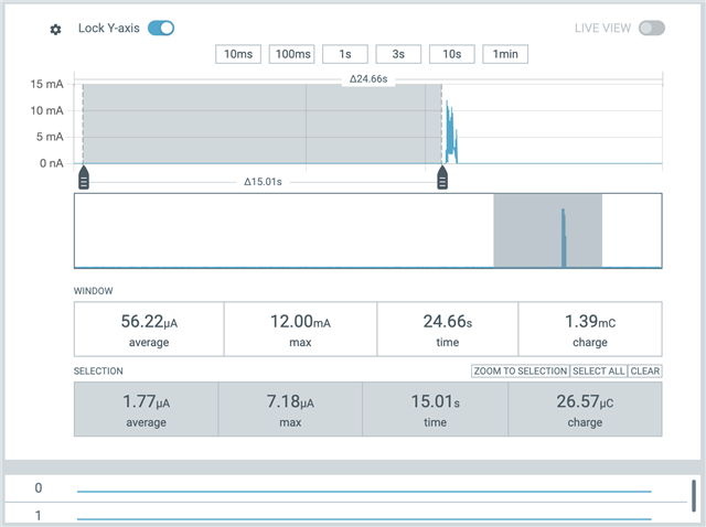
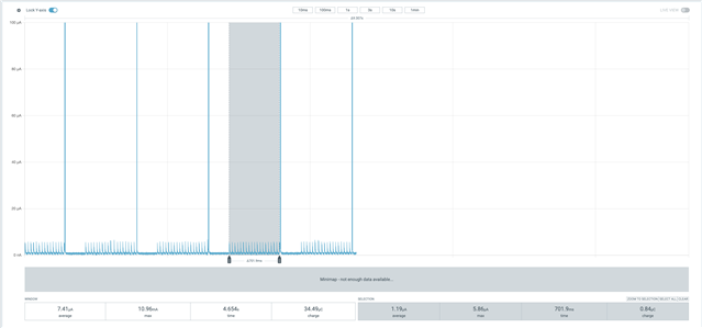
all other things being equal, i find that this (benign) setup adds 0.4uA of *extra* current consumption when sleeping.... (2.1uA without, 2.5uA with)....
i've verified that no SYSCOUNTER[i] is ACTIVE....
i've "discussed" this with your AI (very helpful!!!), but it ultimately said we need to ask a human to clarify.... ;-)